IT and software
State transition diagram (order states, UML)
A UML state machine with transitions, the events and guards that fire them, and the pseudostates that begin and end it
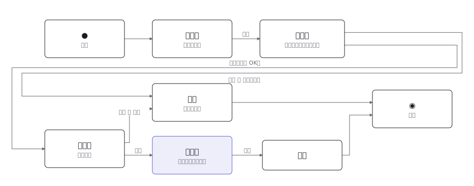
This drawing comes from one YAML file. No shape was moved by hand.
Notes in the source (in Japanese)
状態遷移図は、状態ではなく「遷移」を数える図。状態が 6 つでも、そこへ入る道と出る道が何本あるかで、作る手間が決まる。
「入金[与信 OK]」のように、同じ操作でも条件で行き先が変わる。条件を書かないと、実装したときに分岐が現れて図と合わなくなる。
終わりの状態が 2 つある(完了と取消)。取消へは受付済と入金済の 2 か所から来る(下書きは捨てるだけ、出荷済からは返品という別の流れになる)。どの状態から取消へ行けるかを描き切るのが、この図の本番。
UML の開始は塗りつぶした黒丸だけ、終了は二重丸(黒丸を円で囲む)だけで、箱には入れない。この図では、構成図の箱の中に ● と ◉ を置いて代えている(箱そのものは状態ではない)。
Source (YAML)
examples/gallery/47-状態遷移図.zumen.yaml
More in this field
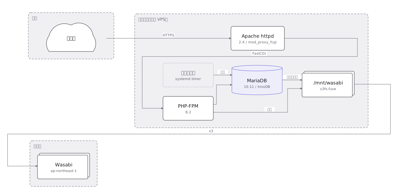 An on-premise server layout rack by rack, with the redundant power feeds and network links drawn as separate paths
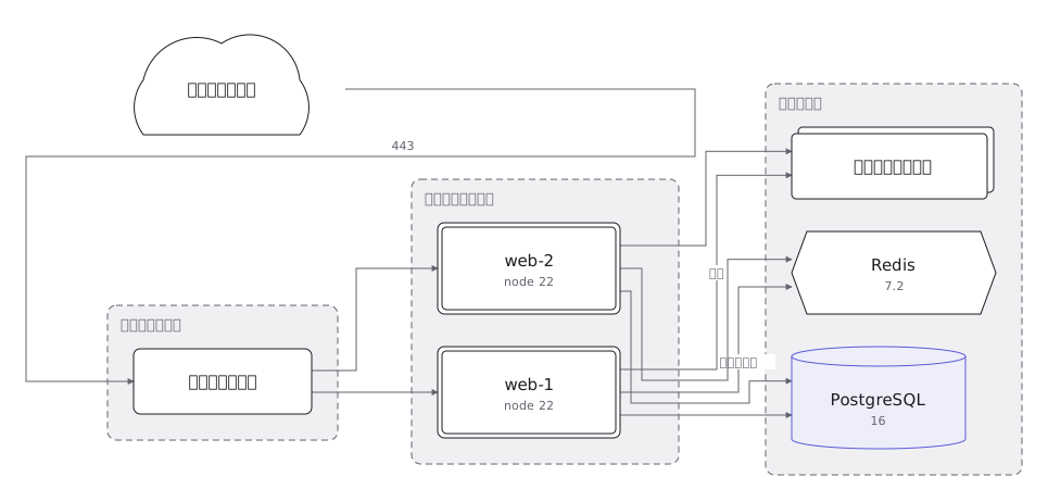 A cloud architecture showing the VPC and its subnets, and where the load balancer, application, database and object store sit
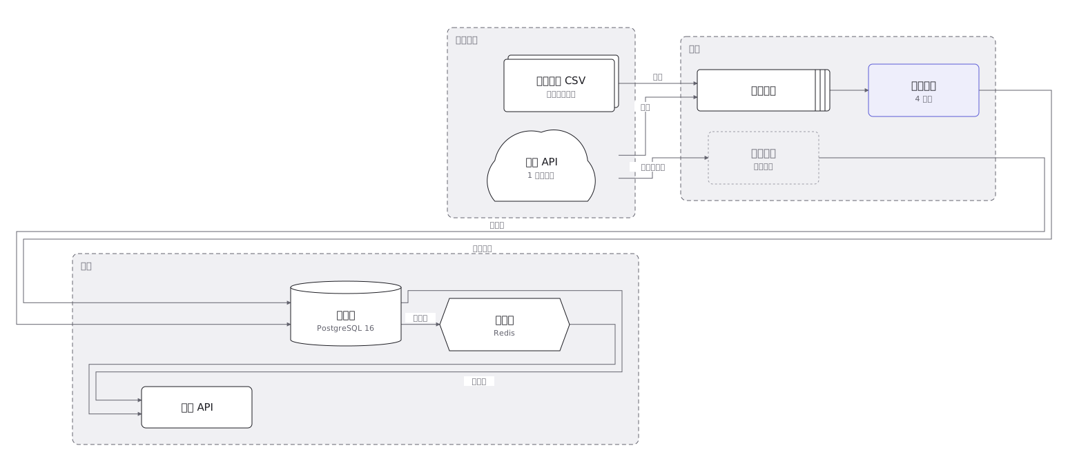 Where data goes from collection through transformation, storage and aggregation to display, and what kind of container holds it at each step
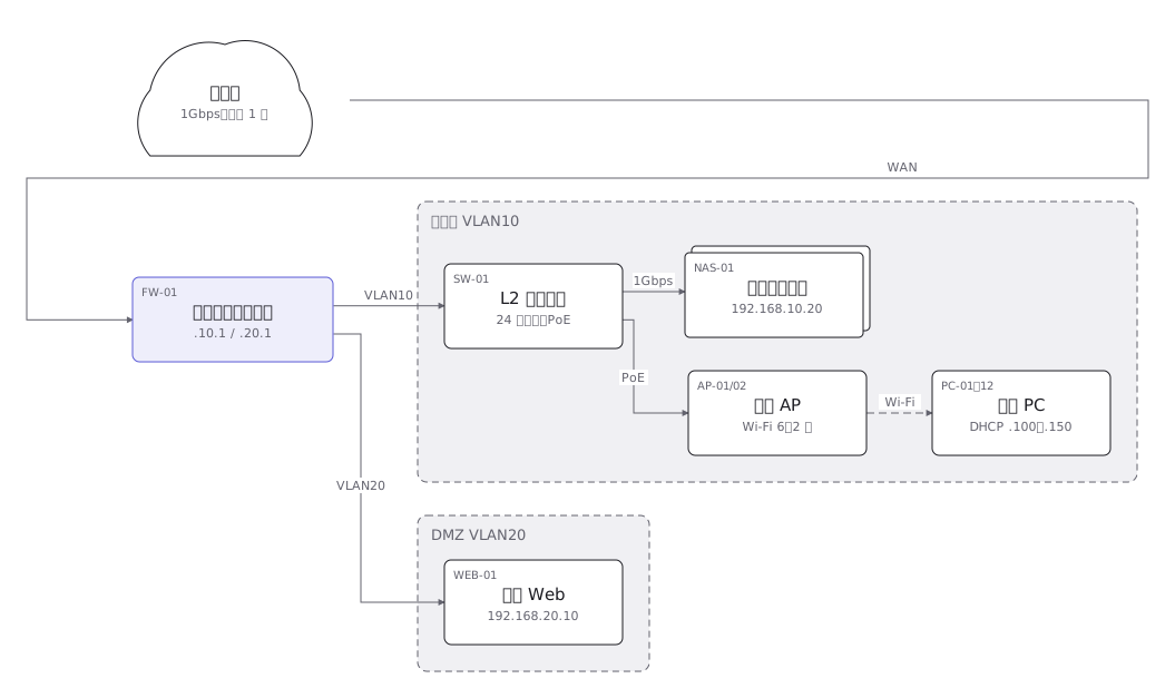 A network layout of the links and equipment between sites, with the address range carried by each segment
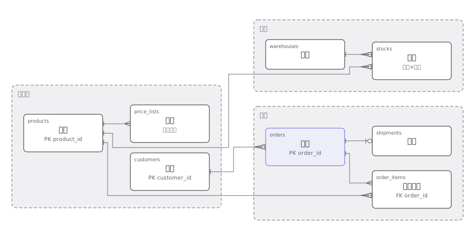 An order management ER diagram with primary and foreign keys, and the one-to-many relationships drawn as crow feet
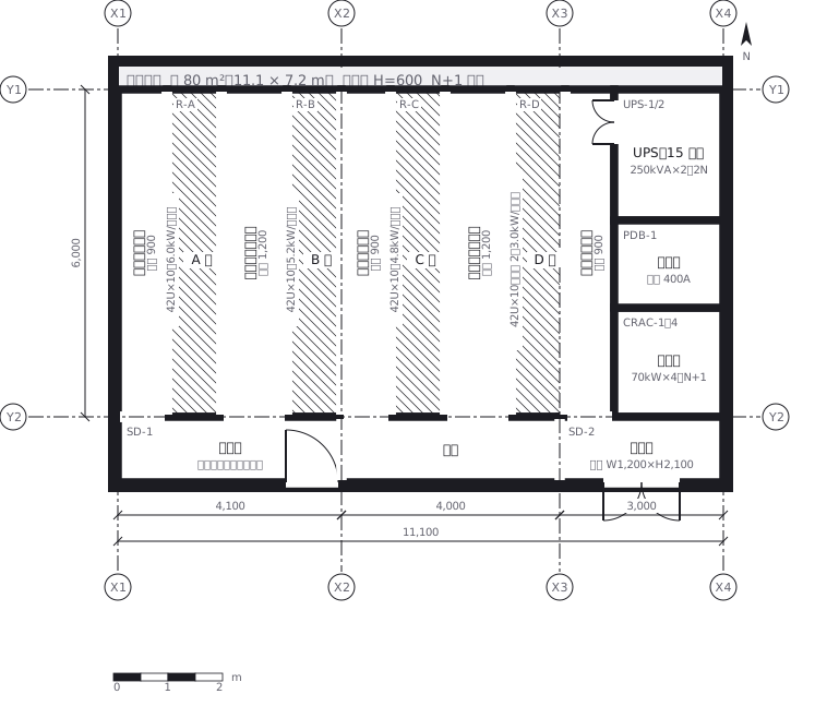 A server room where racks face each other to make hot and cold aisles, with the clearance of each aisle written in
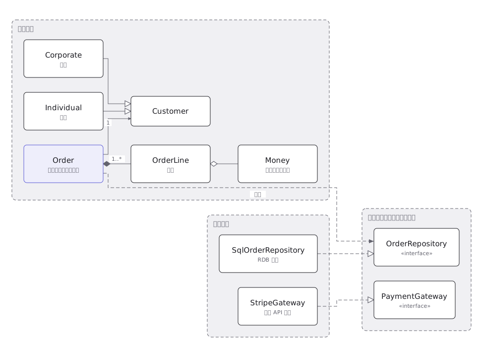 A UML class diagram where inheritance, realisation, association and aggregation are told apart by line type and end symbol
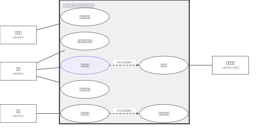 A UML use case diagram with the actors, the use cases, and the include and extend relationships between them