IT and software
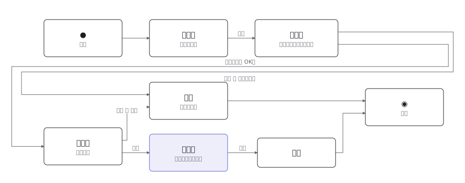
Activity diagram (order processing, UML)
A UML activity diagram from start to end, including decisions, merges and the fork and join of parallel work
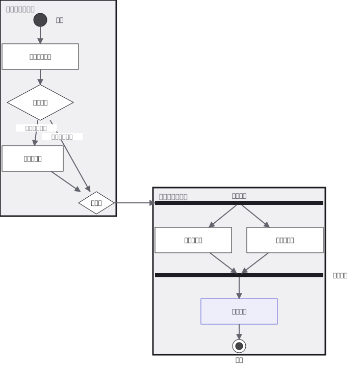
This drawing comes from one YAML file. No shape was moved by hand.
Notes in the source (in Japanese)
レーンがあると、「誰がやるか」が図に入る。受付と倉庫で分けてあるので、レーンをまたぐ線が引き継ぎになる。引き継ぎの数が、そのまま連絡の回数になる。
在庫の有無で分かれた道は、必ずどこかで合流する。合流を描かないと、片方の道がどこへ行くのか分からなくなる。
「どちらか」(デシジョン/マージ = ひし形)と「両方」(フォーク/ジョイン = 太い棒)は別の記号。同じ形で描くと、同時にやってよいのかが読めない。
- フォークに入る線は 1 本だけ(ForkNode の制約)。在庫あり/なしの 2 本は、先にマージ(ひし形)で 1 本にしてからフォークへ入れる- 分岐の条件(ガード)は [ ]で囲んで線に書く- 開始ノードは黒丸、アクティビティ終了は丸の中に黒丸(二重丸は状態機械でも使わない)- フォークから出た 2 つは横に並べる —— 縦に積むと、順にやるように見える
Source (YAML)
examples/gallery/49-アクティビティ図.zumen.yaml
More in this field
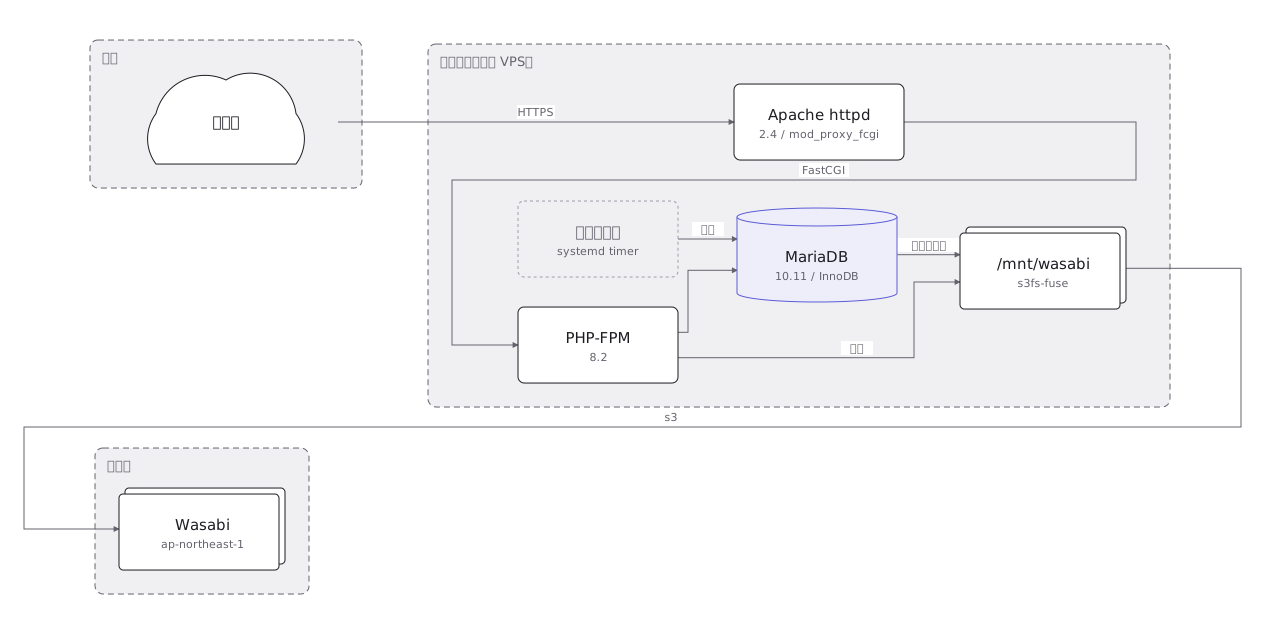 An on-premise server layout rack by rack, with the redundant power feeds and network links drawn as separate paths
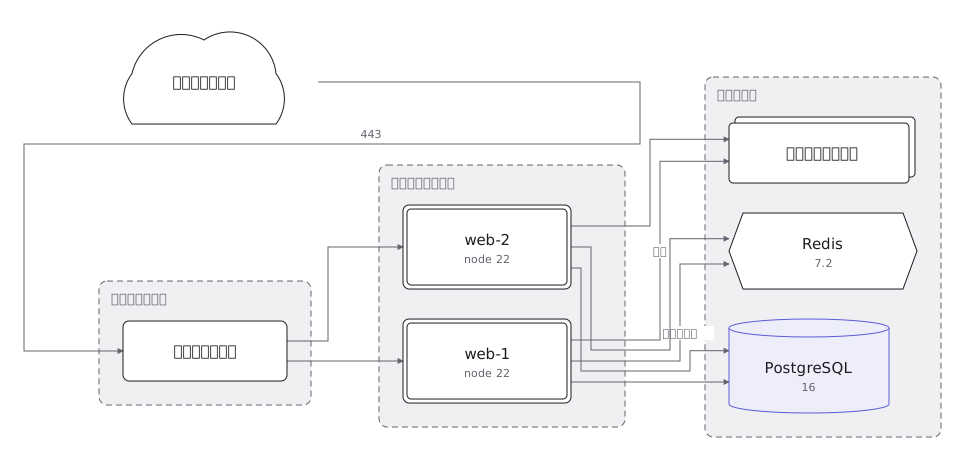 A cloud architecture showing the VPC and its subnets, and where the load balancer, application, database and object store sit
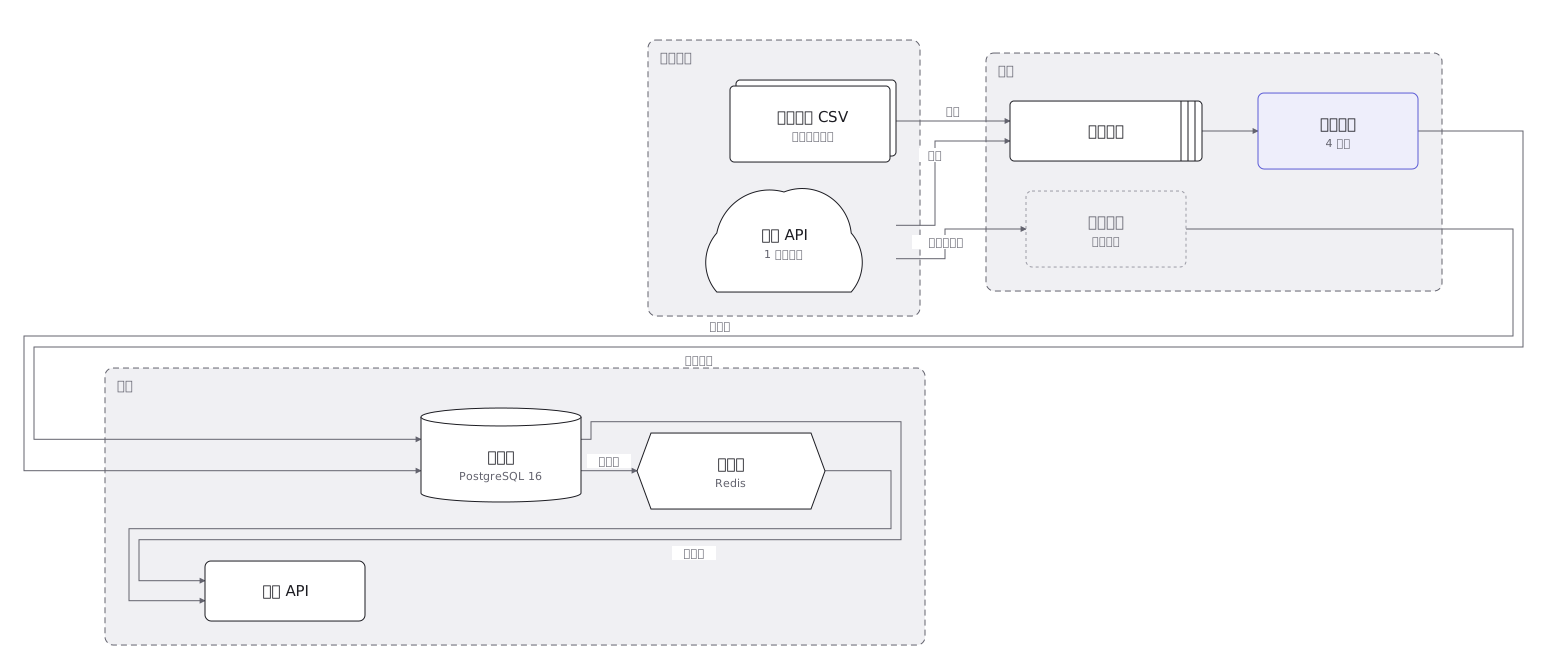 Where data goes from collection through transformation, storage and aggregation to display, and what kind of container holds it at each step
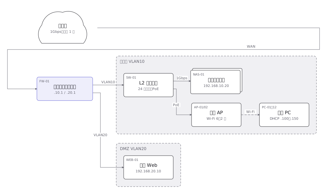 A network layout of the links and equipment between sites, with the address range carried by each segment
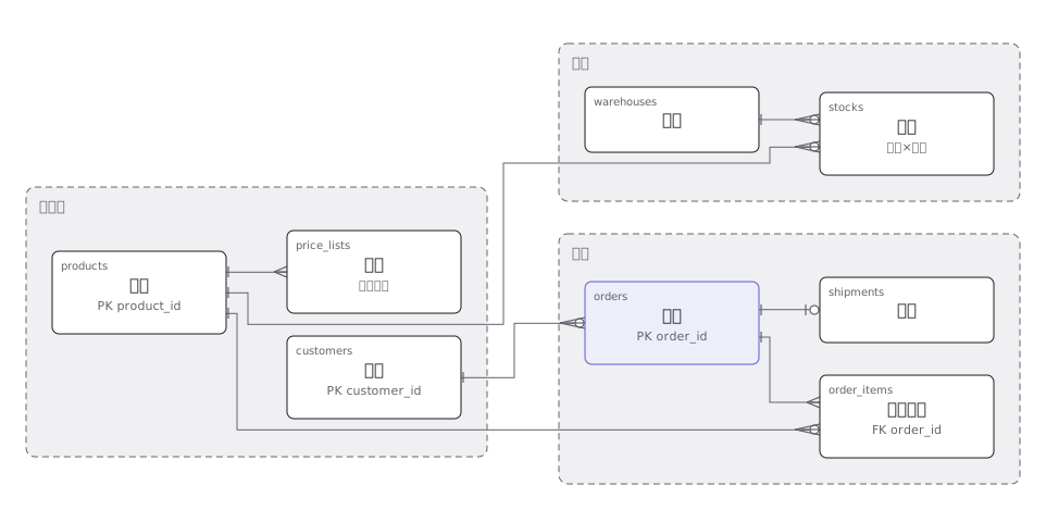 An order management ER diagram with primary and foreign keys, and the one-to-many relationships drawn as crow feet
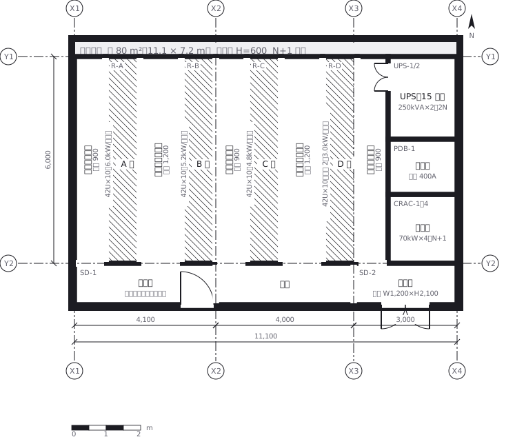 A server room where racks face each other to make hot and cold aisles, with the clearance of each aisle written in
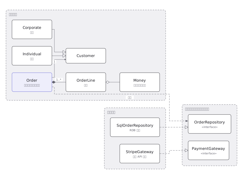 A UML class diagram where inheritance, realisation, association and aggregation are told apart by line type and end symbol
 A UML state machine with transitions, the events and guards that fire them, and the pseudostates that begin and end it