Services and electrical
Substation single-line diagram
A substation single-line diagram from the incoming supply through disconnector, breaker and transformer to the low voltage boards
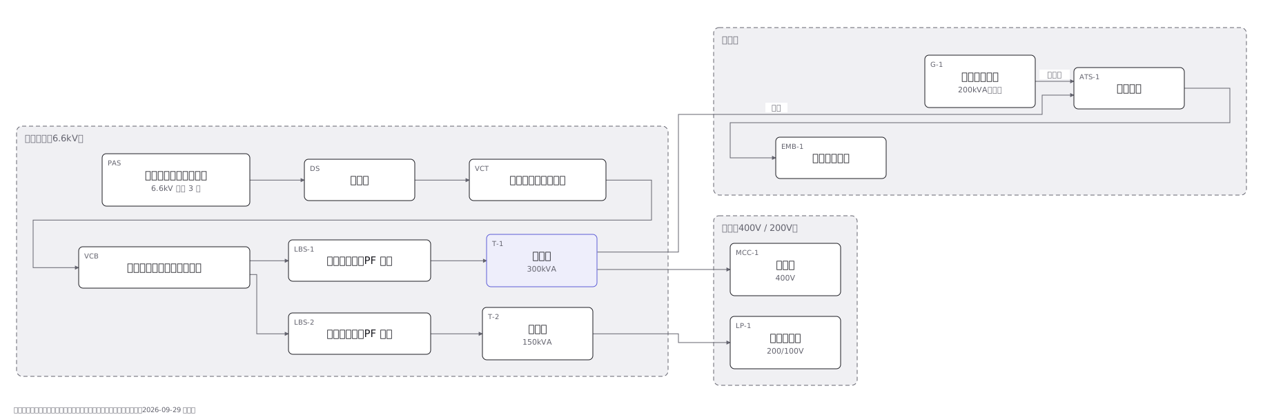
This drawing comes from one YAML file. No shape was moved by hand.
Notes in the source (in Japanese)
「単線」は、線が 1 本という意味ではない。三相 3 線も、単相 3 線も、1 本の線で描く。この図が運ぶのは電線の本数ではなく、機器の順番と、系統の分かれ方。
6.6kV をそのまま受けて、自分の変圧器で 400V / 200V へ落とす。区分開閉器(PAS)から先は需要家の持ち物(責任分界点)。だから保護も点検も自分でやる。
並びは 区分開閉器 → 断路器 → 取引用計器用変成器 → 主遮断装置 → 変圧器ごとの開閉器。変圧器の合計が 300kVA を超えると、開閉器+限流ヒューズ(PF・S 形)では受けられず、遮断器で切る CB 形になる。この図は 300+150=450kVA なので VCB を置く。変圧器ごとの開閉器は、限流ヒューズ付きの負荷開閉器(LBS・PF 付)。出典:日本電気技術者協会「高圧自家用受電設備の保護について」https://www.jeea.or.jp/course/contents/05204/ (取得 2026-09-29)
発電機は常用の系統と並ばない。自動切替(ATS)で切り替わった先の非常用分電盤だけが生きる。何を非常用にするかは、この図で決まる。
Source (YAML)
examples/gallery/19-受変電の結線.zumen.yaml
More in this field
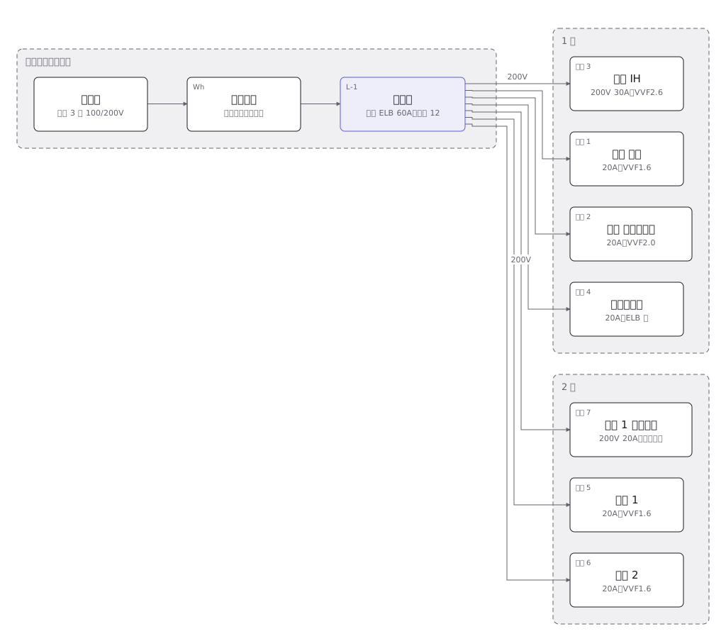 A house wiring layout from the service entrance to the consumer unit, then breaker by breaker to the sockets and lights in each room
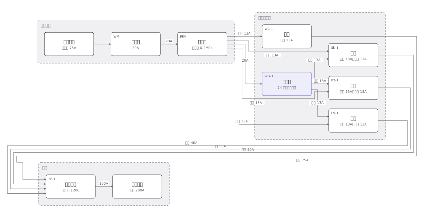 The four plumbing systems of a house — cold supply, hot supply, drainage and venting — separated out fixture by fixture
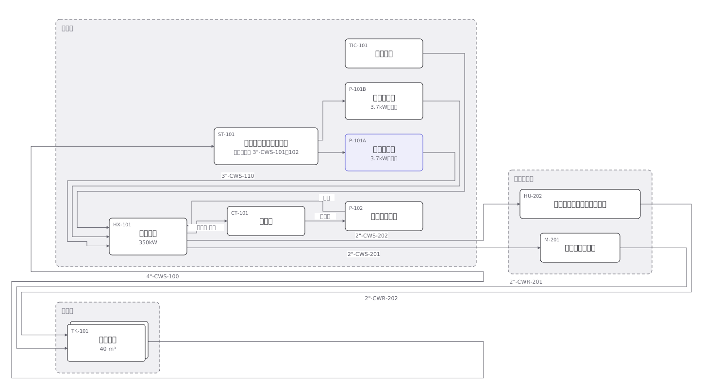 A cooling water P&ID where pumps, heat exchangers, valves and instruments are joined by pipes distinguished by line type
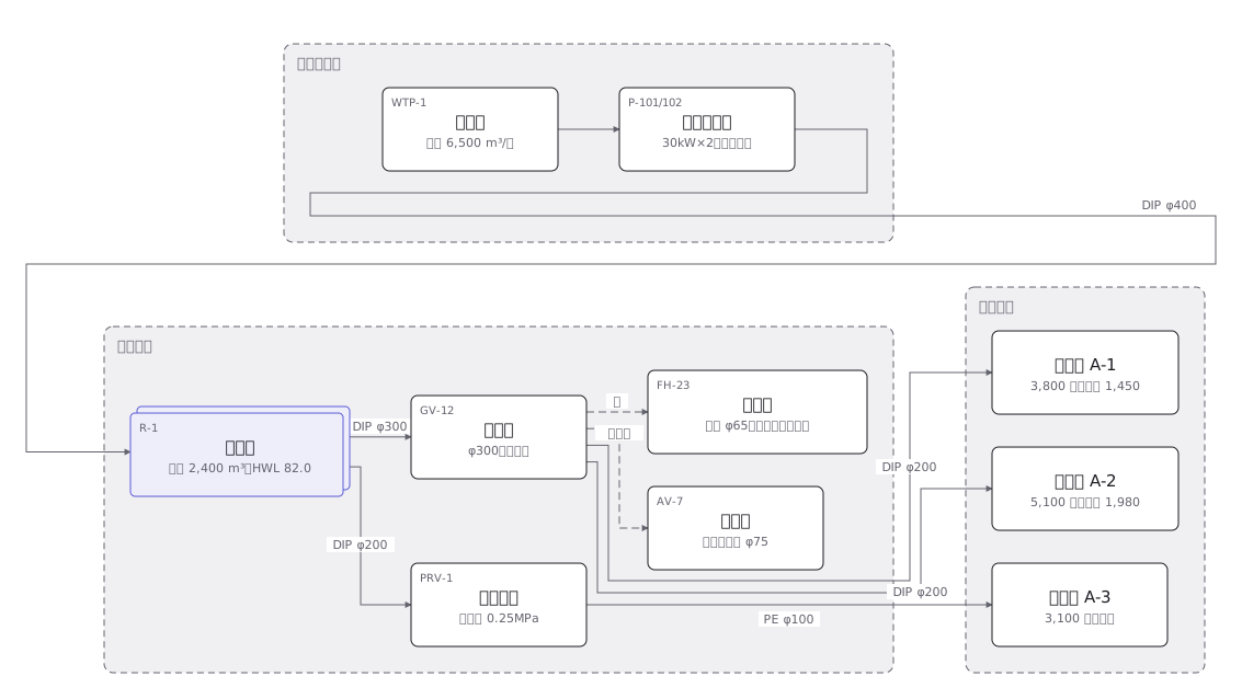 A town water distribution network from treatment works through service reservoirs and trunk mains to each supply zone, with the ground level of every zone
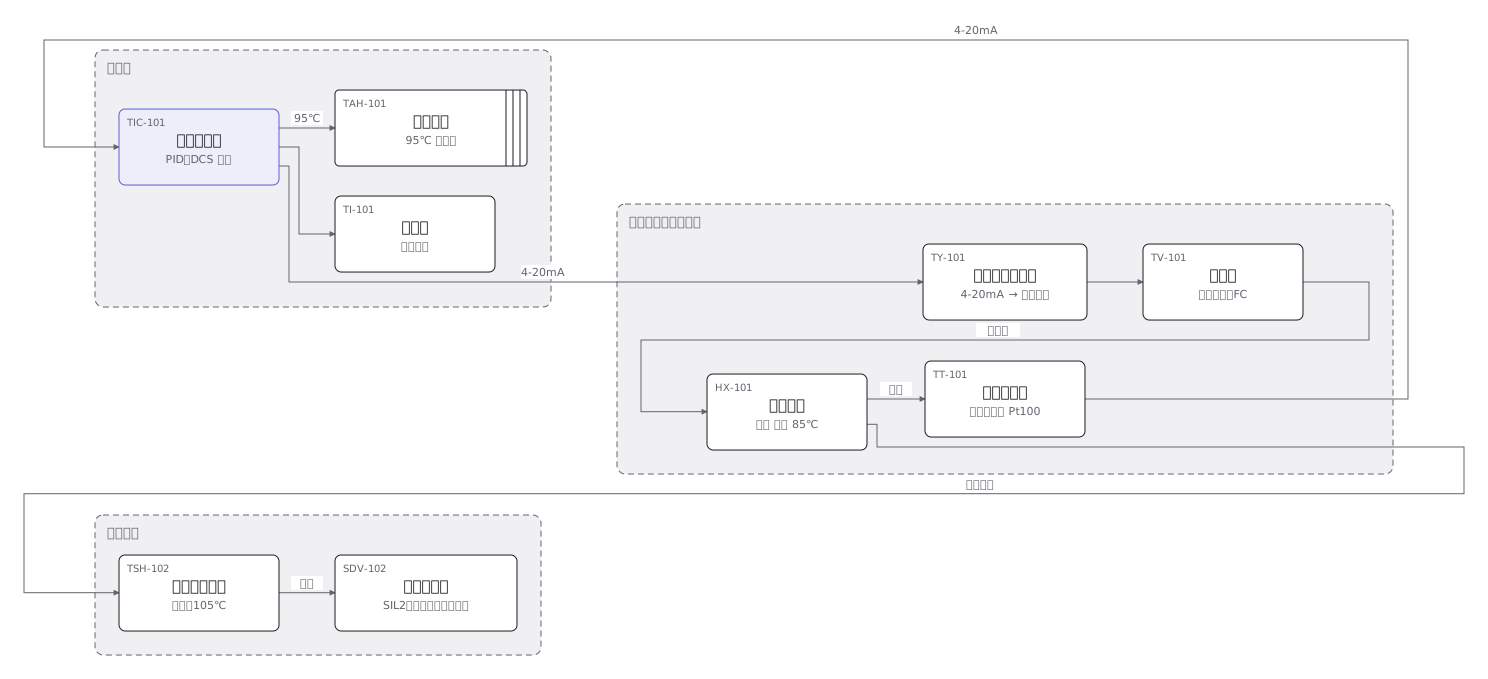 An instrument loop from sensing element through transmitter and controller to final element, every device carrying its ISA tag
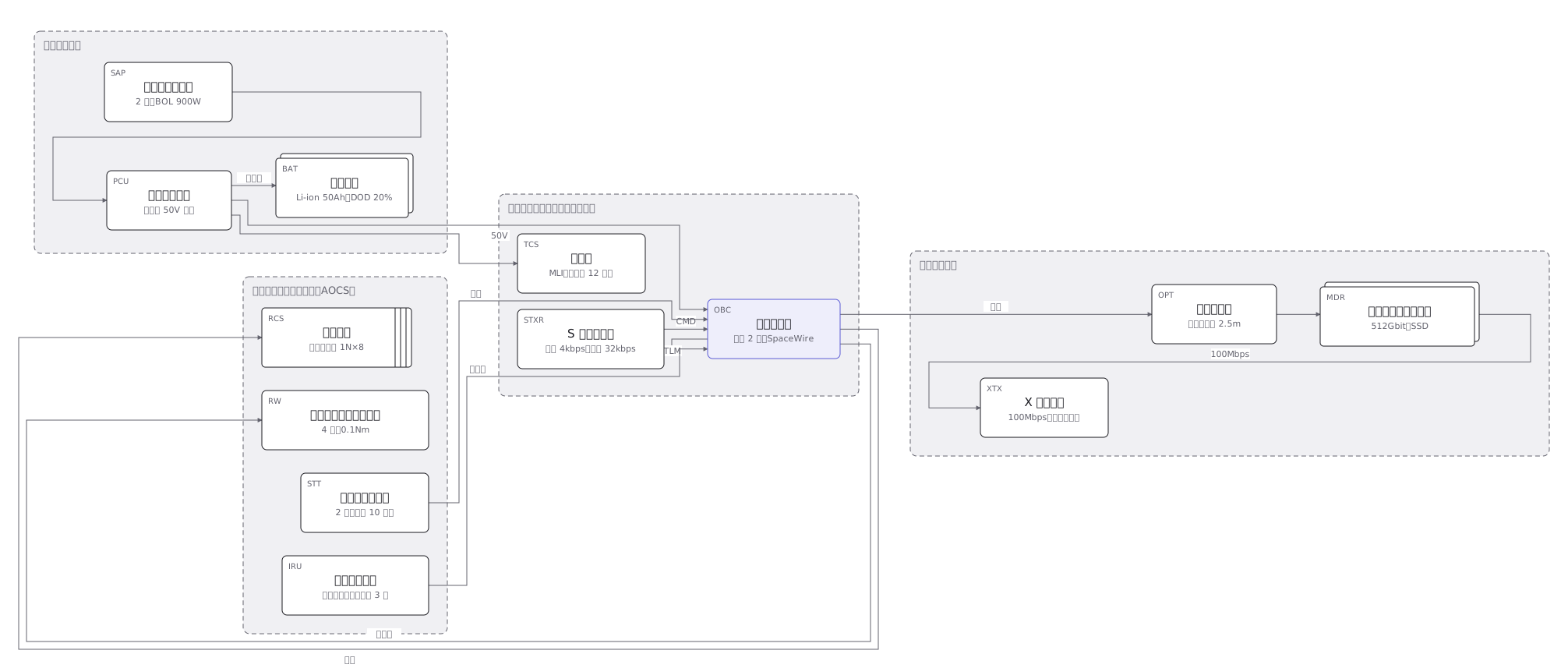 The subsystems of a 150kg satellite and how they connect: power, communications, attitude control, data handling and the mission payload
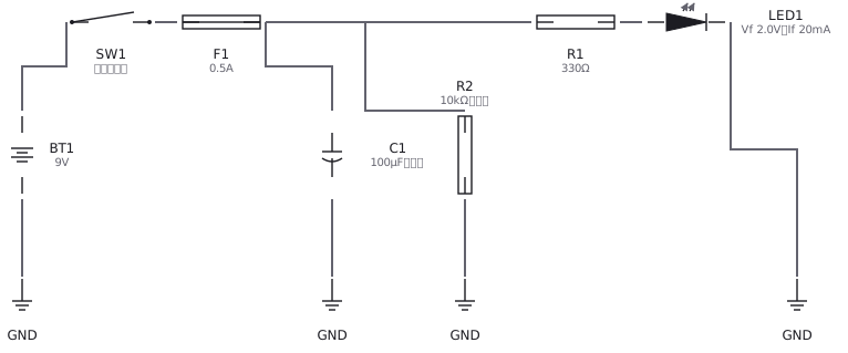 An LED circuit drawn with IEC and JIS symbols: supply, resistor, LED and switch
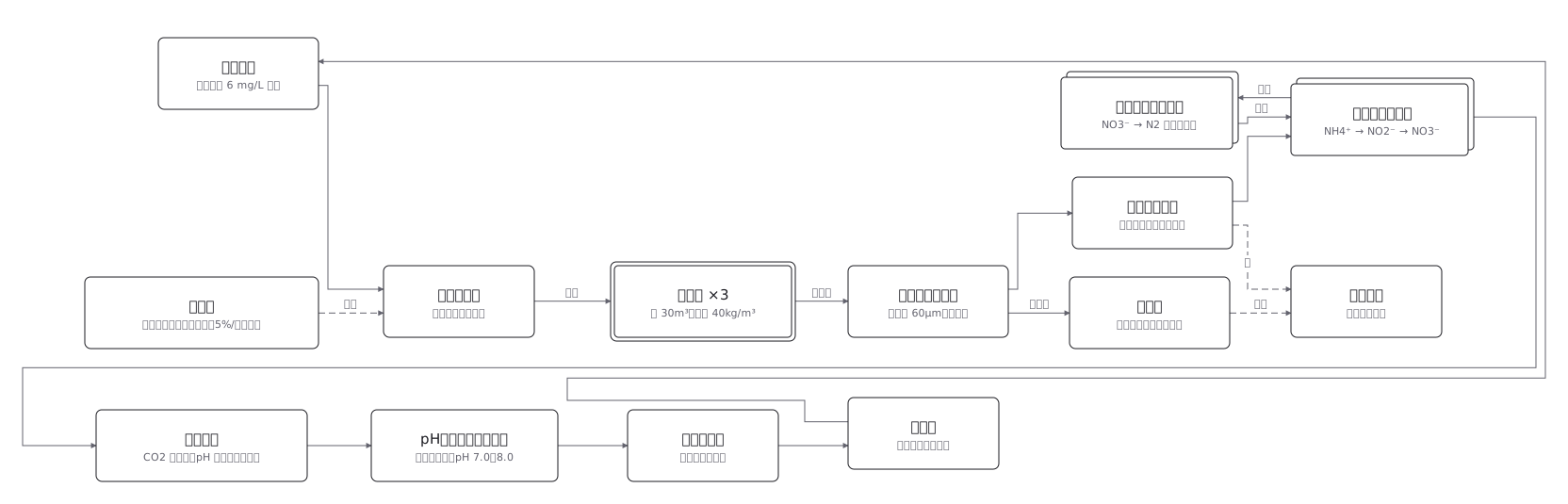 Land-based aquaculture: the water is cleaned, not replaced