Services and electrical
Instrument loop diagram (TIC-101, heat exchanger outlet temperature control)
An instrument loop from sensing element through transmitter and controller to final element, every device carrying its ISA tag
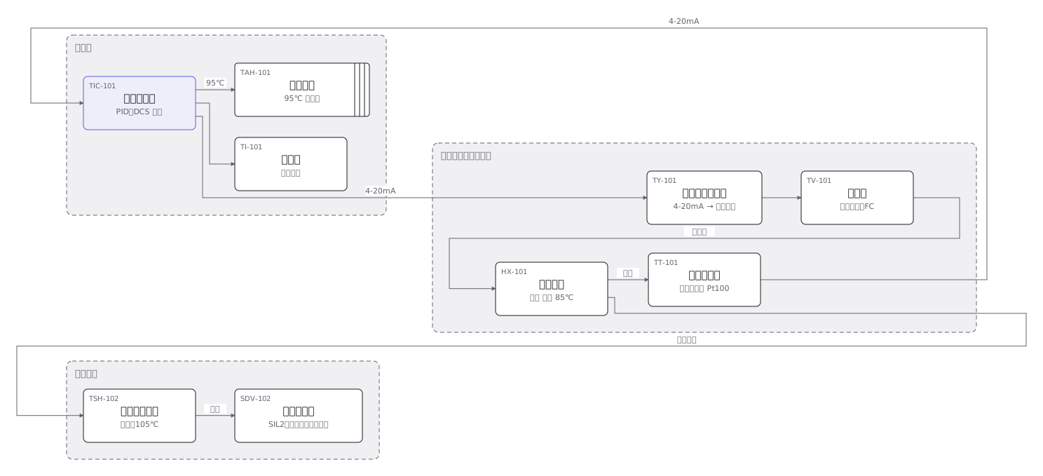
This drawing comes from one YAML file. No shape was moved by hand.
Notes in the source (in Japanese)
ループ図は、1 つの制御ループだけを描く。P&ID がプラント全体なら、ループ図はその中の 1 本を最後まで追う図。
変量の文字(T = 温度)+機能の文字(I = 指示、C = 調節)+個別番号。JIS Z 8204:1983 は、これを直径 10mm の丸の中へ、上に文字記号・下に個別番号と決めている。調節計の 4〜20mA を空気の信号へ直すポジショナは変換器なので、機能の文字は Y(TY-101。JIS Z 8204:1983 の機能記号)。
0mA を「測定値ゼロ」に使わない。0 は断線。下限を 4mA にしてあるので、線が切れたことと、値が下がったことを区別できる。
同じ発信器から取ると、それが壊れたときに両方とも効かない。温度スイッチが独立して測温しているのは、そのため。
Source (YAML)
examples/gallery/38-計装ループ図.zumen.yaml
More in this field
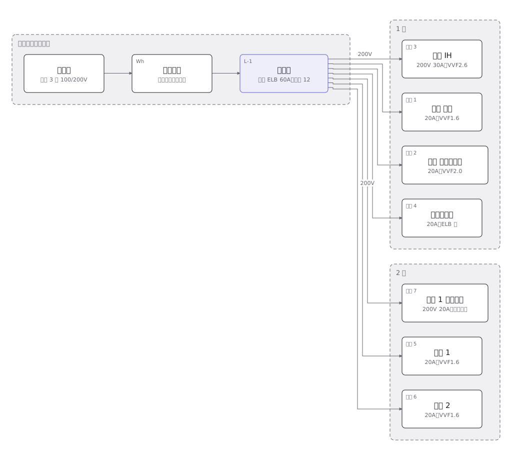 A house wiring layout from the service entrance to the consumer unit, then breaker by breaker to the sockets and lights in each room
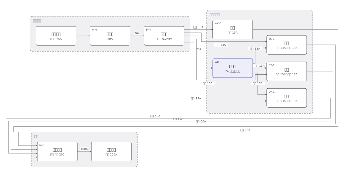 The four plumbing systems of a house — cold supply, hot supply, drainage and venting — separated out fixture by fixture
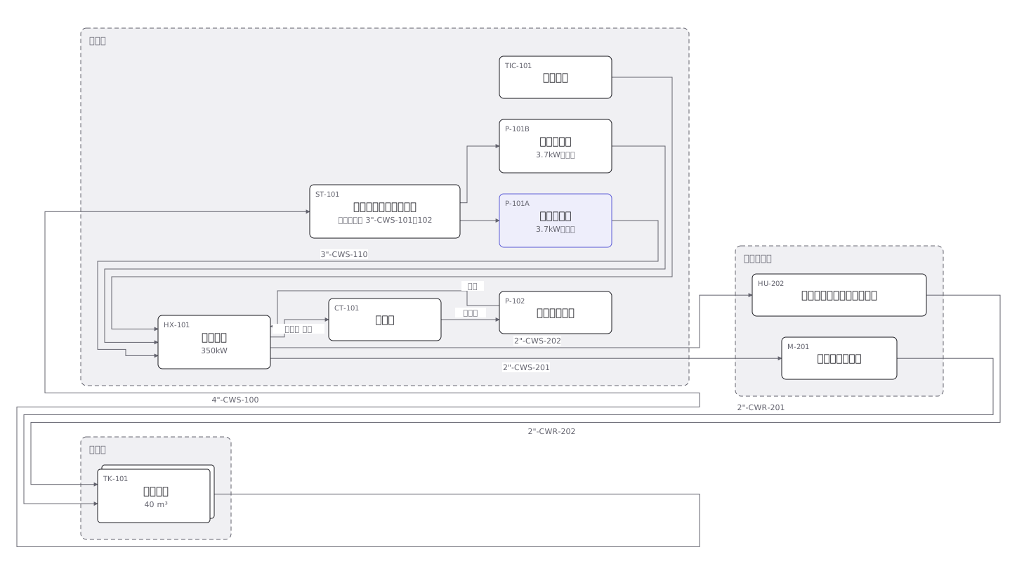 A cooling water P&ID where pumps, heat exchangers, valves and instruments are joined by pipes distinguished by line type
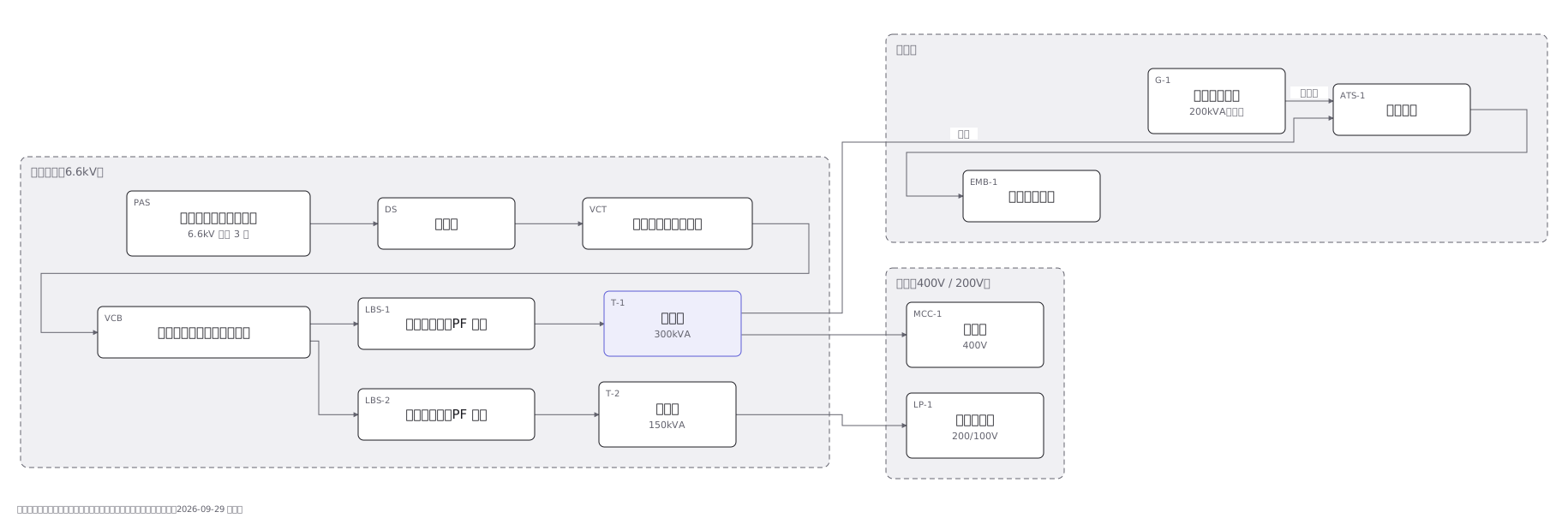 A substation single-line diagram from the incoming supply through disconnector, breaker and transformer to the low voltage boards
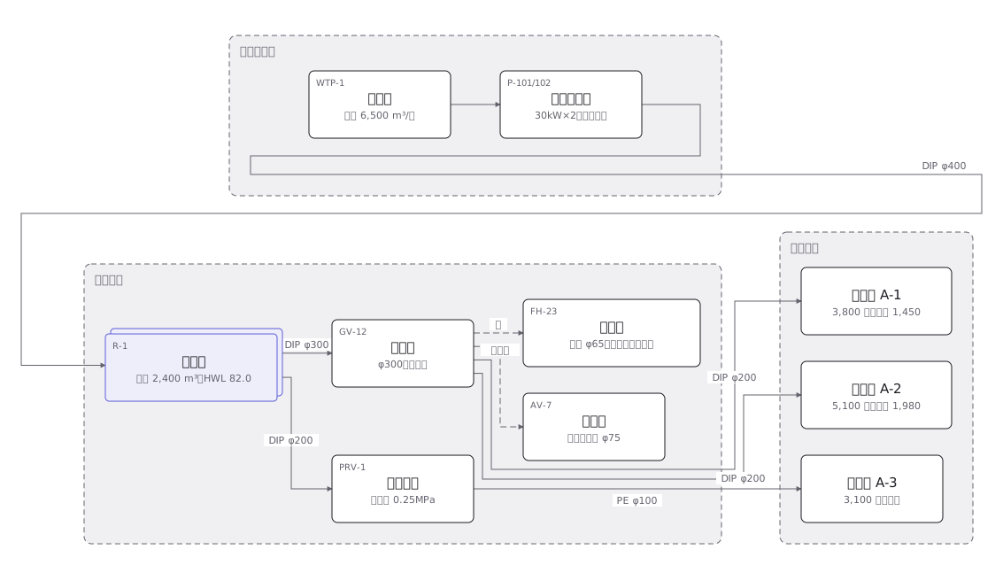 A town water distribution network from treatment works through service reservoirs and trunk mains to each supply zone, with the ground level of every zone
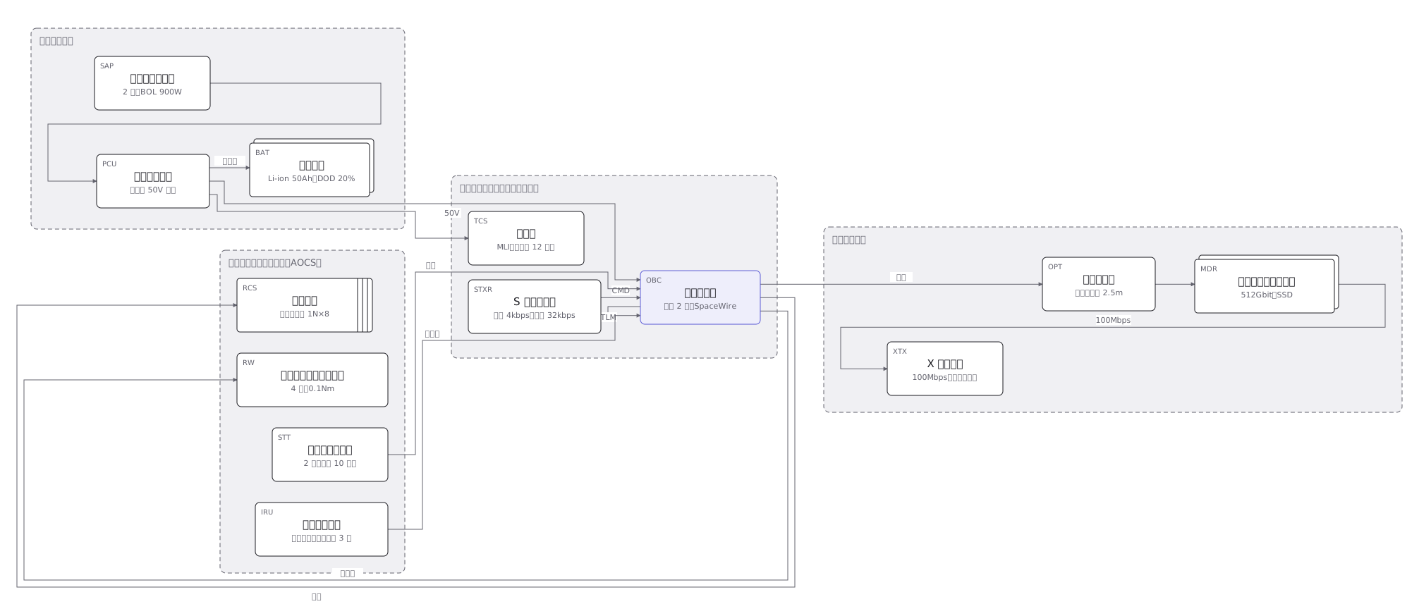 The subsystems of a 150kg satellite and how they connect: power, communications, attitude control, data handling and the mission payload
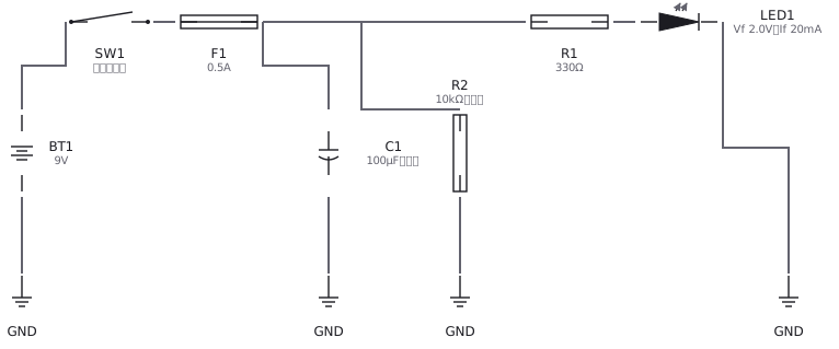 An LED circuit drawn with IEC and JIS symbols: supply, resistor, LED and switch
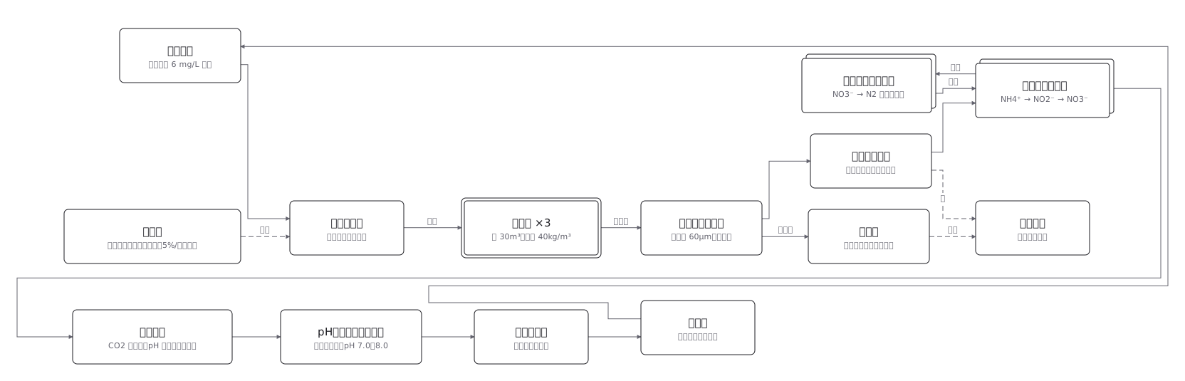 Land-based aquaculture: the water is cleaned, not replaced