Services and electrical
East 50 Hz and west 60 Hz (four frequency converter stations linking 2.1 GW)
Japan's two mains frequencies: 50 Hz in the east and 60 Hz in the west, split along prefecture lines and the Fuji River, with a close-up of central Japan showing the four frequency converter stations (Sakuma, Shin-Shinano, Higashi-Shimizu, Hida-Shinano) that link the grids by turning AC into DC and back, 2.1 GW in all and 3 GW planned for FY2027.
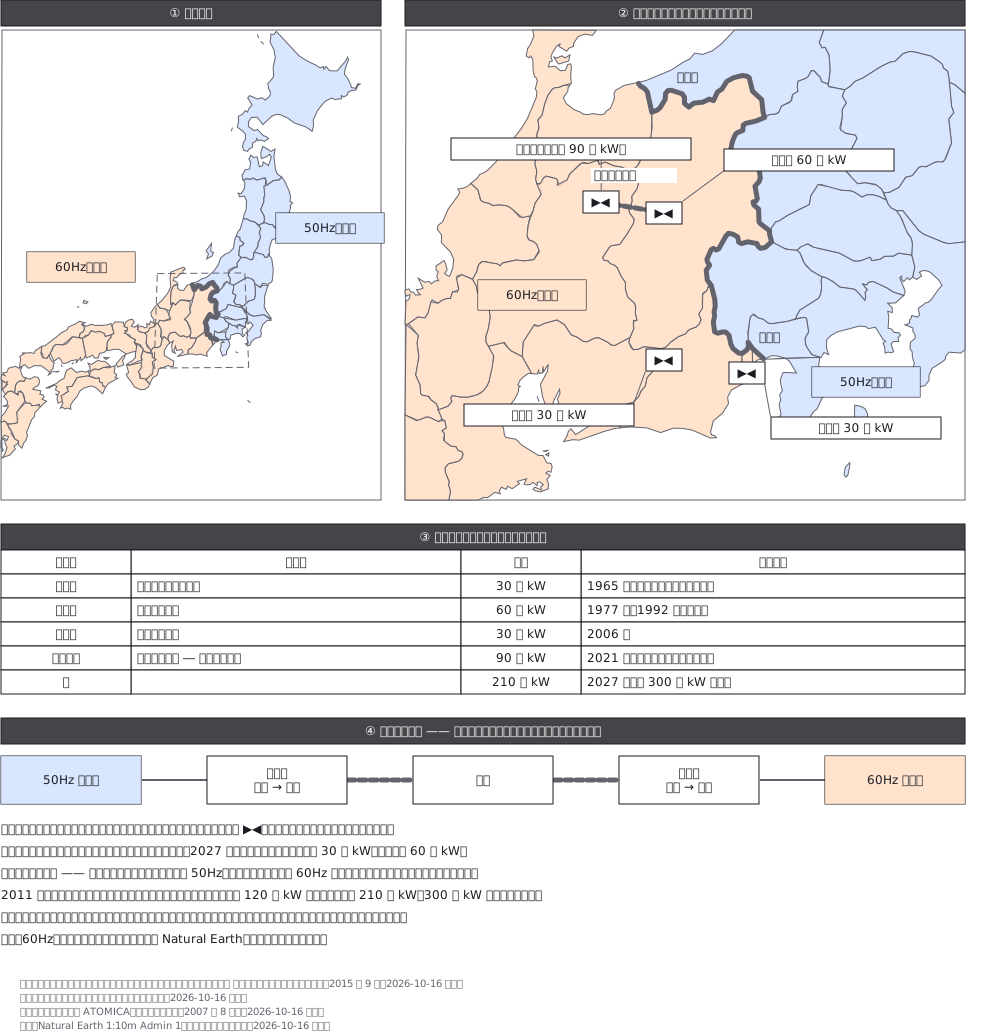
This drawing comes from one YAML file. No shape was moved by hand.
Notes in the source (in Japanese)
日本の電気は、東が 50Hz、西が 60Hz。 境をまたいで電気を送るには、いったん直流にして周波数を変える。
決まり・値 ——
| 変換所 | 所在地 | 容量 | 運転開始 | 出典 |
|---|---|---|---|---|
| 佐久間 | 静岡県浜松市天竜区佐久間町 | 30 万 kW | 1965 年 10 月(わが国初の 50・60Hz 連系) | 送配電網協議会、ATOMICA |
| 新信濃 | 長野県朝日村 | 60 万 kW | 1977 年 12 月、1992 年 5 月に増設 | 同上 |
| 東清水 | 静岡県静岡市 | 30 万 kW | 2006 年 3 月 | 同上 |
| 飛騨信濃 | 岐阜県高山市(飛騨変換所)― 長野県朝日村(新信濃) | 90 万 kW | 2021 年 3 月 | 送配電網協議会、広域機関 |
- 計 210 万 kW(2021 年。それまでは 120 万 kW)。2027 年度に 300 万 kW(佐久間地点に 30 万 kW、東清水に 60 万 kW。広域機関「東京中部間連系設備に係る広域系統整備計画」の工事概要)- 増強の目的は「大規模事故・災害発生時に供給力が大幅に喪失した際の、50Hz/60Hz 地域間での安定供給確保」(同)- 東西で違うわけ:明治初期に東京はドイツ製の 50Hz、大阪はアメリカ製の 60Hz の発電機を採った(ATOMICA)- 記号 ▶◀ は、広域機関の資料の凡例で「周波数変換所、BTB」(同じ敷地で交流 → 直流 → 交流)
都道府県の輪のうち、50Hz の県と 60Hz の県が点を共有している辺をつないで境の線にした(糸魚川の西から山梨・静岡の県境まで)。静岡は富士川で切り、東を 50Hz にした(川は 3 点で大づかみ。内房の地名で中ほどを取った)。塗りは半透明なので、静岡は重ねて塗らず、川の東と西に切り分けてから塗った。
境は本当は県境ではなく、電力会社の供給区域の境。 この図は県と富士川で丸めている。変換所の位置は町の位置(OpenStreetMap で引いた)で、変電所そのものの位置ではない。
- 北海道と本州の間の直流連系(周波数はどちらも 50Hz。容量の推移を一次資料で確かめきれなかった)- 沖縄(60Hz)。各エリアの地域間連系線(交流)- 送電線の経路・電圧(飛騨信濃の直流送電線は、2 つの変換所を直線で結んだだけ)
Source (YAML)
examples/gallery/398-東の50Hzと西の60Hz-周波数変換所.zumen.yaml
More in this field
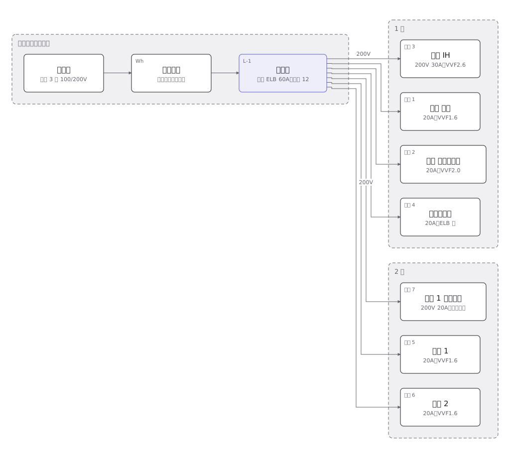 A house wiring layout from the service entrance to the consumer unit, then breaker by breaker to the sockets and lights in each room
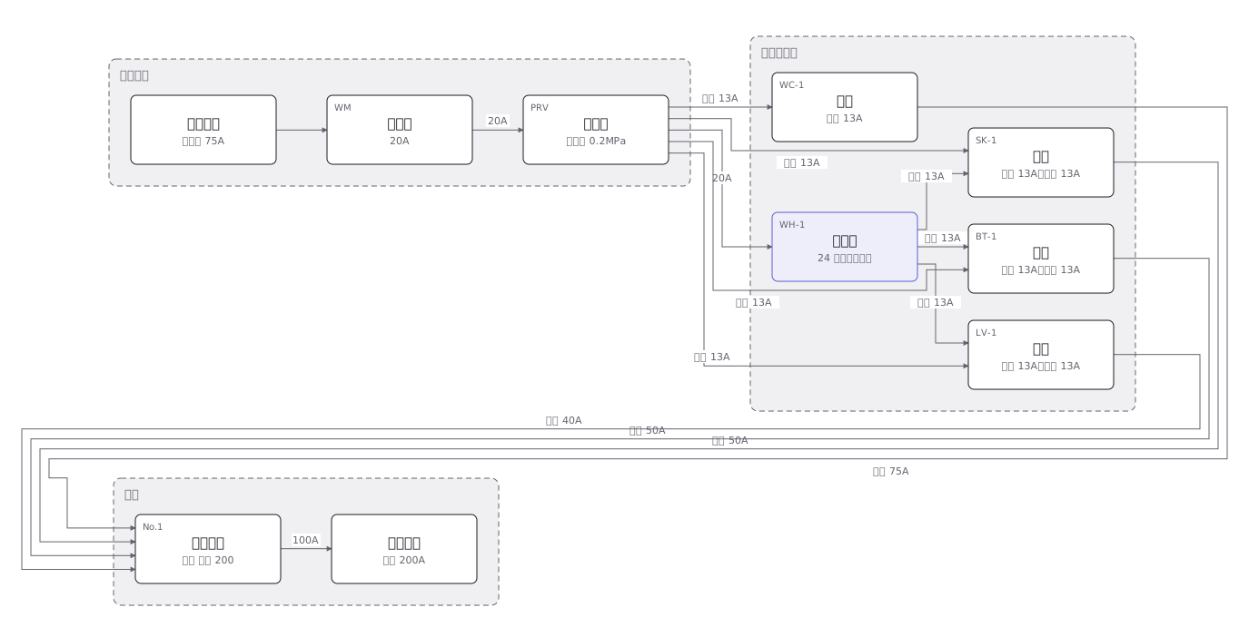 The four plumbing systems of a house — cold supply, hot supply, drainage and venting — separated out fixture by fixture
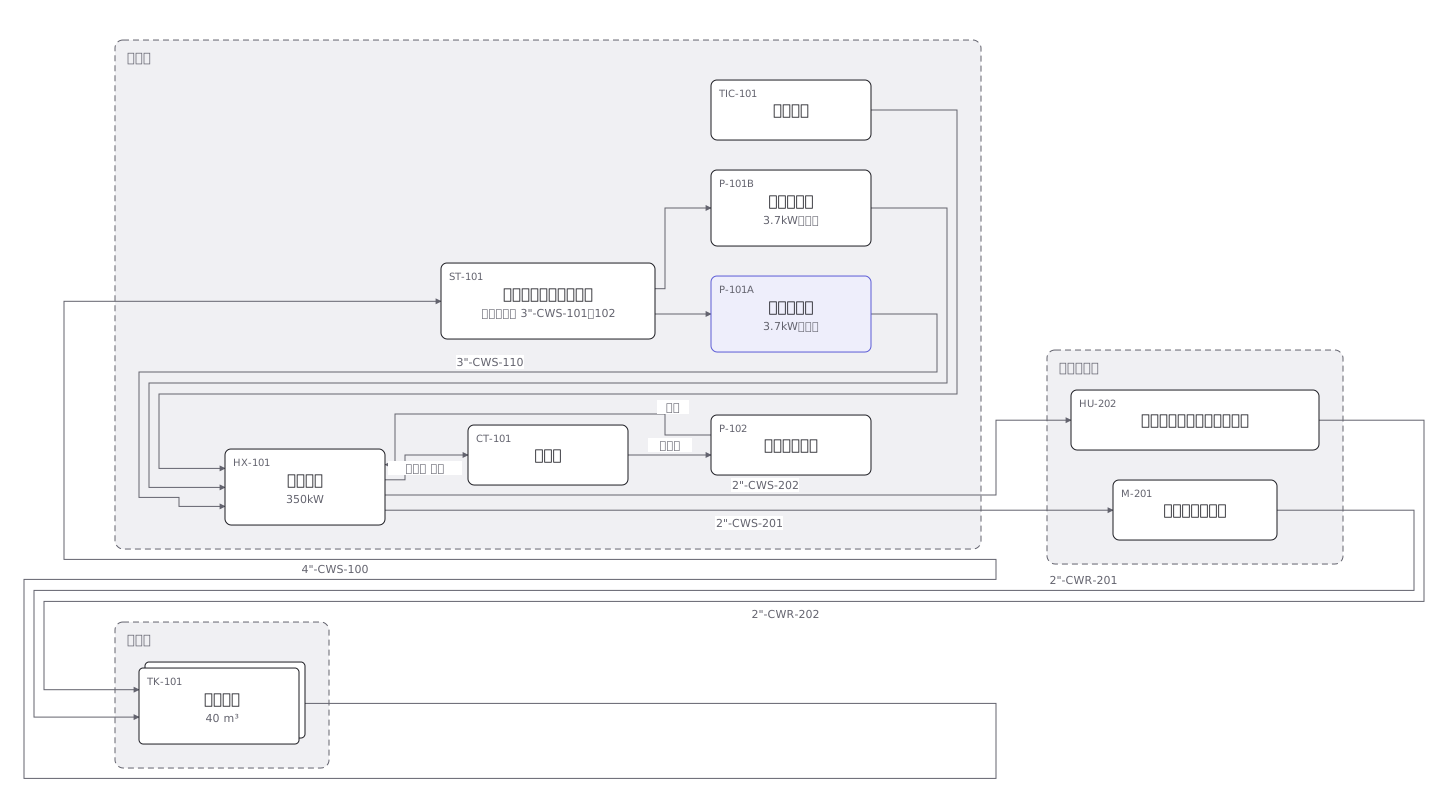 A cooling water P&ID where pumps, heat exchangers, valves and instruments are joined by pipes distinguished by line type
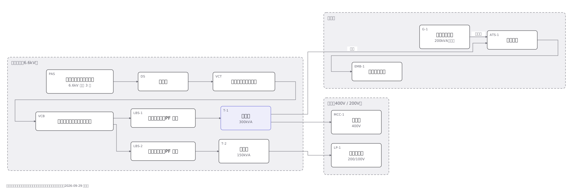 A substation single-line diagram from the incoming supply through disconnector, breaker and transformer to the low voltage boards
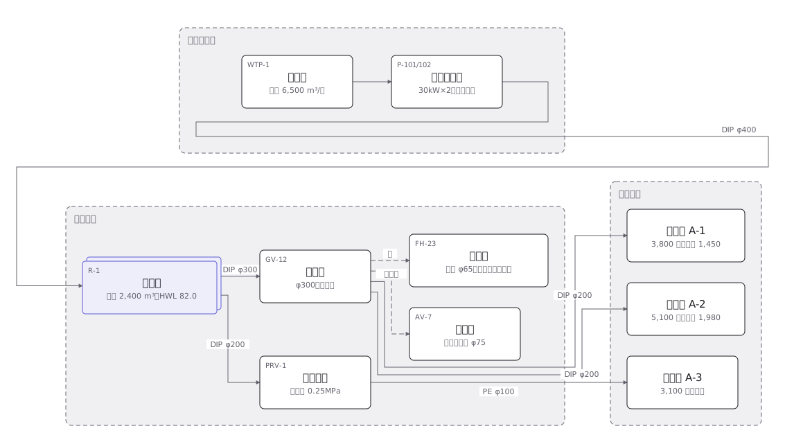 A town water distribution network from treatment works through service reservoirs and trunk mains to each supply zone, with the ground level of every zone
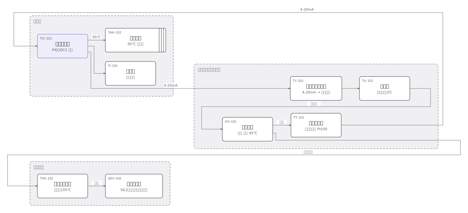 An instrument loop from sensing element through transmitter and controller to final element, every device carrying its ISA tag
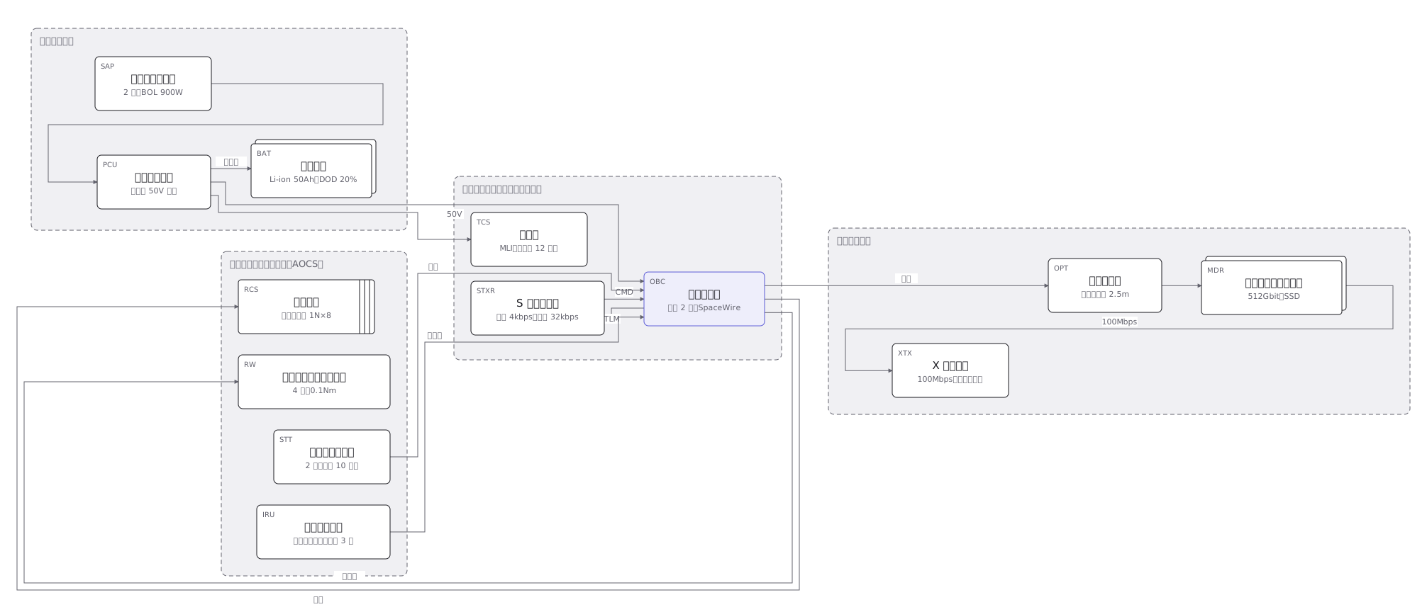 The subsystems of a 150kg satellite and how they connect: power, communications, attitude control, data handling and the mission payload
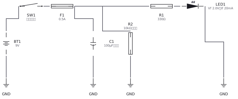 An LED circuit drawn with IEC and JIS symbols: supply, resistor, LED and switch