Transit and transport
City road No. 3 horizontal alignment plan (No. 0 to No. 9, W = 8,800)
A road alignment where straights and a circular curve join up, with the intersection point and tangents, chainage ticks and the curve parameters; the centreline is a chain line and the road edges are solid
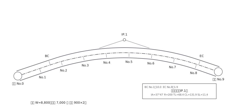
This drawing comes from one YAML file. No shape was moved by hand.
Notes in the source (in Japanese)
道路の平面線形。曲がっていること自体が内容なので、直角では代用できない。道路中心線は一点鎖線、車道端(幅員線)は実線で描く(国土交通省「CAD 製図基準」令和 7 年 12 月版の道路平面図のレイヤ:道路中心線=構造物基準線・一点鎖線。https://www.cals-ed.go.jp/mg/wp-content/uploads/cad8.pdf 取得 2026-10-02)。同じ基準の平面図の記載事項 —— 道路中心線、曲線の起終点(BC・EC)、IP の位置と曲線半径 R・接線長 TL・曲線長 CL・交角 IA・正矢 SL、道路幅員線 —— を図に入れてある。IP へ向かう接線は、車道端の外側だけを細線で描いた(道路の中は中心線と重なるため)。測点は 20m ごとで、中心線を横切る短い線が測点の位置。曲線は IP.1 の単曲線 1 つ(R=200m、交角 IA=37°47′)で、接線長 TL=R·tan(IA/2)=68.4m、曲線長 CL=R·IA=131.9m、SL=R·(1/cos(IA/2)−1)=11.4m(IP から曲線の中点まで。基準の表では「正矢(S.L)」と書くが、式は外線長 secant length。R·(1−cos(IA/2))=10.8m の中央縦距とは別)。BC は No.1+10.0(30m)なのでEC は 30+131.9=161.9m=No.8+1.9。IP は BC と EC から接線を TL だけ延ばした交点。図は 1m=4.5px で、R・接線・測点の間隔もこの縮尺で計算して描いてある。
Source (YAML)
examples/gallery/61-道路の平面線形図.zumen.yaml
More in this field
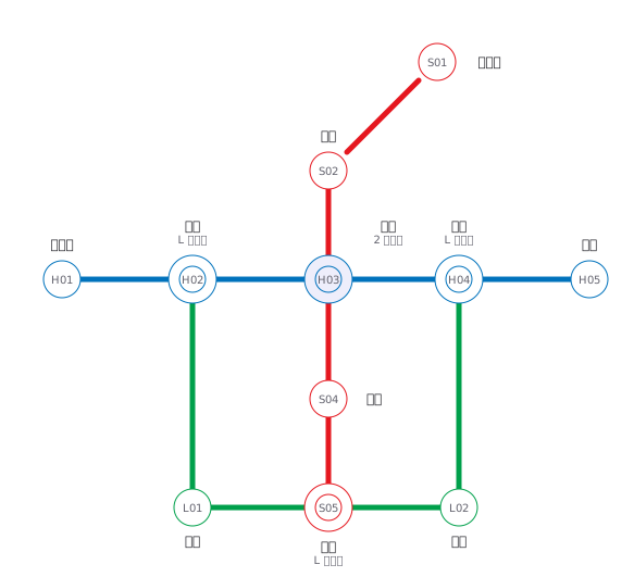 A fictional transit map of three lines told apart by colour and station numbering, drawn only in horizontal, vertical and 45° segments, with interchange stations marked by a double circle
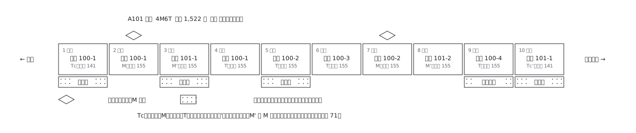 A ten-car commuter train set out car by car: which are motored and which are trailers, where the pantographs are, and what each car carries inside
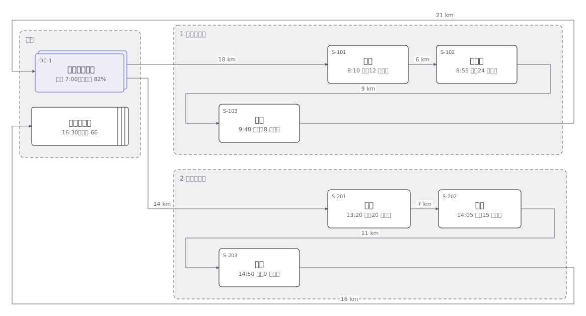 Delivery rounds for one two-tonne van split into a morning and an afternoon run: the order of calls and the stops themselves
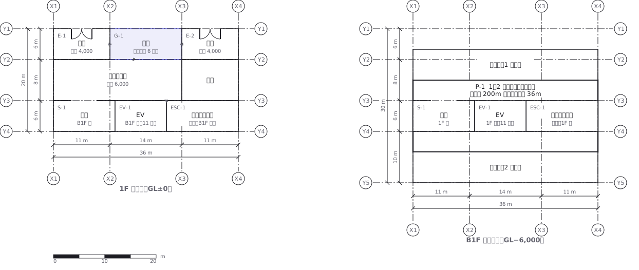 A station on two levels — ground floor and concourse — showing how the gates, stairs, lifts and exits line up with each other
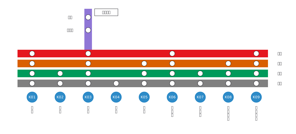 Stopping pattern chart: a band per service, a circle per stop
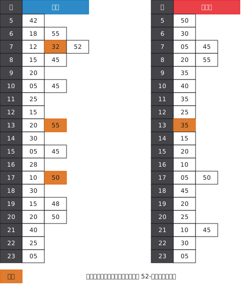 A station timetable with hours down the side and minutes across, weekday and weekend separated, and train types shown by symbol
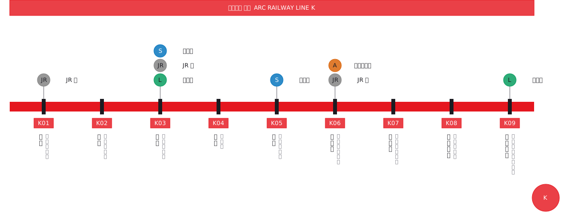 Interchange guide with station names set vertically
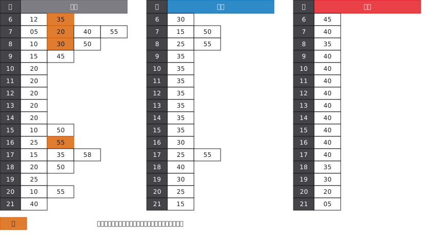 A bus stop timetable in three columns — weekday, Saturday, Sunday and holiday — with the departure minutes listed under each hour