Building and civil
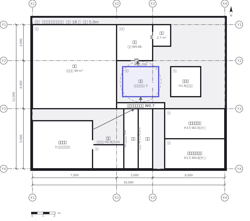
Second-floor framing plan (reinforced concrete)
A reinforced concrete framing plan for a second floor, with the grid lines and the mark of every column, girder, beam and slab
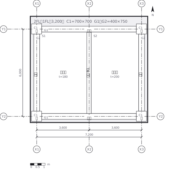
This drawing comes from one YAML file. No shape was moved by hand.
Notes in the source (in Japanese)
伏図は「上から見下ろして、その階の床を描く」図。2 階床伏図なら、描いてあるのは 1 階と 2 階の間にある梁と柱。見えている床板ではなく、その下の骨を描く。
C1 は 1 階も 2 階も C1。通し番号ではなく種類の名前なので、同じ断面の柱はどこにあっても同じ符号になる。
大梁(G)は柱と柱をつなぎ、小梁(B)は大梁と大梁をつなぐ。荷重の行き先が違うので、同じ「梁」でも別の記号にする。1 px = 20 mm。柱芯の間隔 180px が 1 スパン 3,600mm になる。柱・梁の幅も同じ縮尺で描く(C1 700 = 35px、G 400 = 20px、B1 300 = 15px)。2026-09-29 まで柱を 1,120mm 角で描いていて、表の 700×700 と合っていなかった。
X2 の小梁 B1 は、北の G1 と南の G1 をつなぐ(大梁から大梁へ)。ここに柱を立てると、B1 は柱に取り付く梁=大梁になり、上の定義と食い違うので、X2 の南に置いていた柱 C2 を外した(南の G1 は X1〜X3 の 1 本)。
Source (YAML)
examples/gallery/17-躯体の伏図.zumen.yaml
More in this field
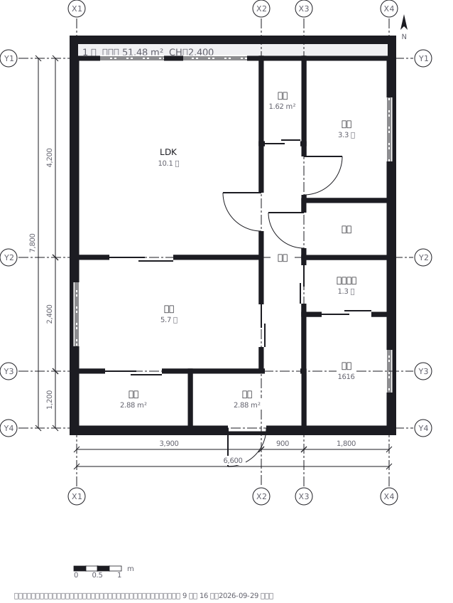 A two-bedroom apartment plan with room dimensions, which way each door swings, and where the wet rooms and storage sit
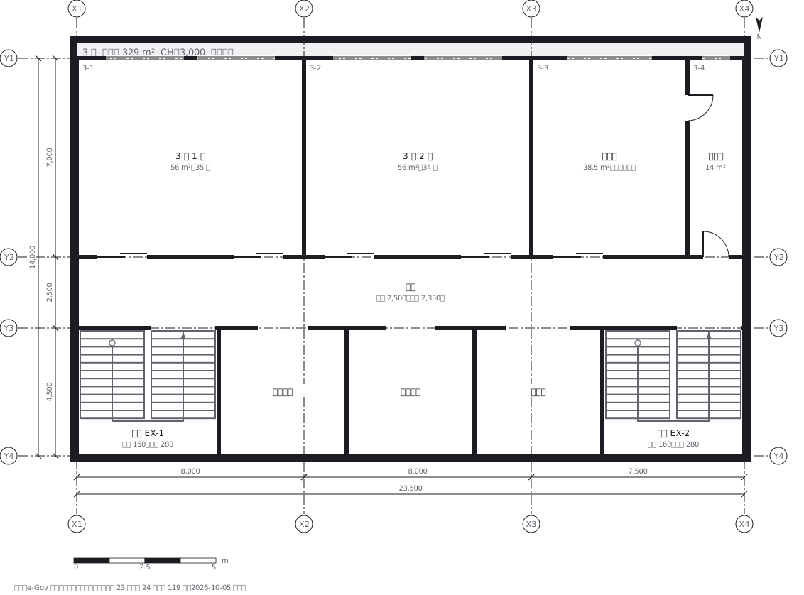 School floor plan (walls, door swings, grid lines, dimensions)
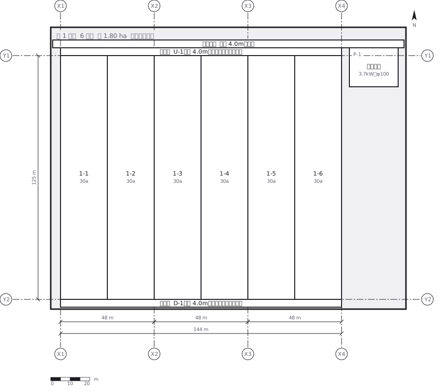 A farmland consolidation plan laying out 30-are plots, with the irrigation channels, the drainage channels and the farm roads that serve them
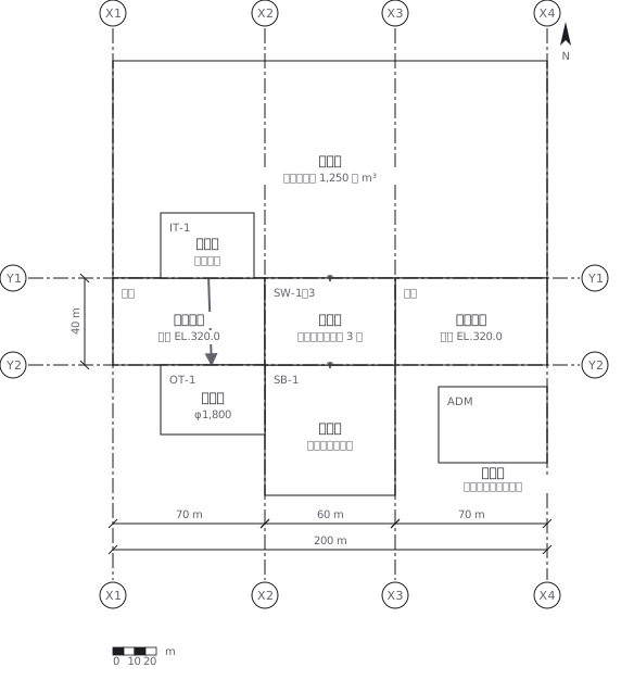 The plan of a concrete gravity dam: the body, the spillway, the intake works and the access road for maintenance
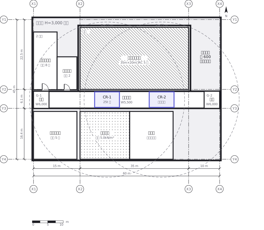 Site logistics plan with the crane radius
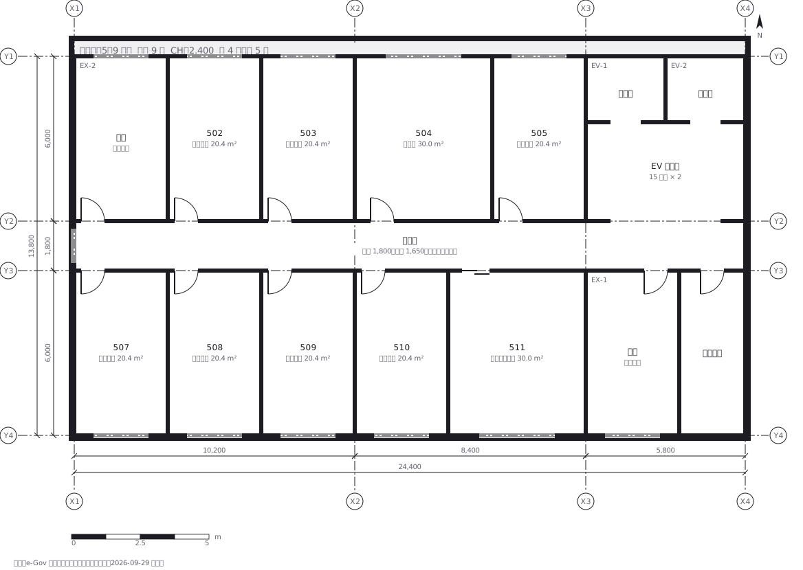 The typical floor of a business hotel with nine rooms, a central corridor, two direct stairs, and two lifts with their hall
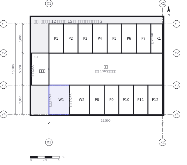 A surface car park set out for fourteen cars, with bay dimensions, aisle width and where the entrance and exit sit
 The garden path to a tea house: outer and inner roji, with the stepping stones, water basin, middle gate, waiting bench and planting