Building and civil
Gear meshing (the module sets the tooth size, not the diameter)
What sets the size of a gear tooth is the module, not the diameter — the diameter is what comes out of it, and so is the centre distance, which means the shaft positions are fixed the moment the gears are chosen. Two gears mesh if the module and the pressure angle match; the tooth counts and diameters can differ freely, and the speed ratio is just the inverse ratio of the tooth counts.
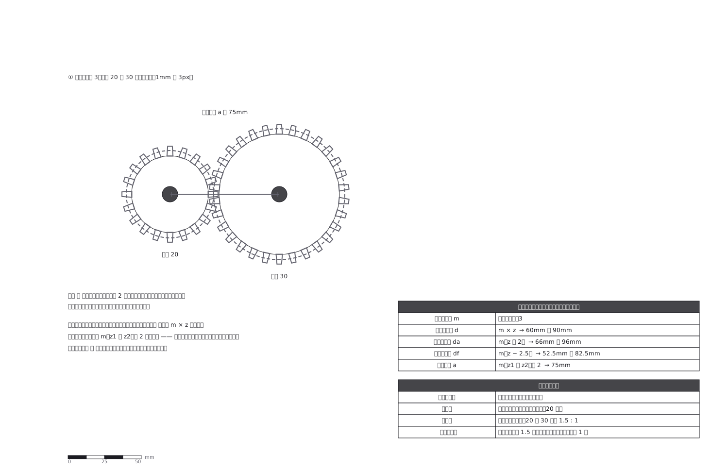
This drawing comes from one YAML file. No shape was moved by hand.
Notes in the source (in Japanese)
歯の大きさを決めるのはモジュール m で、直径ではない。 直径はその結果。
基準円直径 d = m × z、歯先円直径 da = m(z + 2)、歯底円直径 df = m(z − 2.5)、そして中心距離 a = m(z1 + z2)/ 2。
この図は m = 3、z = 20 と 30。d は 60mm と 90mm、da は 66mm と 96mm、df は 52.5mm と 82.5mm、a は 75mm。
軸の位置は、歯車を選んだ時点で決まっている(転位の無い標準歯車のとき。転位すれば中心距離をずらせる —— JIS B 1701-1 の基準ラック:歯末 1.00m・歯元 1.25m・圧力角 20°)。
モジュールが同じで、圧力角が同じ(20 度)。歯数が違っても、直径が違っても、この 2 つが揃えばかみ合う。逆に、どちらかが違えば、どんなに寸法を合わせてもかみ合わない。
歯数の比と基準円直径の比は等しいので、回転比は歯数の比の逆数。20 と 30 なら 1.5 : 1 —— 小さいほうが 1.5 回まわる間に、大きいほうが 1 回。
歯形は模式(インボリュート曲線は描いていない)。破線が基準円で、2 つの基準円が接する所がかみ合い点。
はめあいは見本 243、ねじや継手の側は見本 180。JIS B 1701-1 の版は確かめていない。
Source (YAML)
examples/gallery/333-歯車のかみ合い.zumen.yaml
More in this field
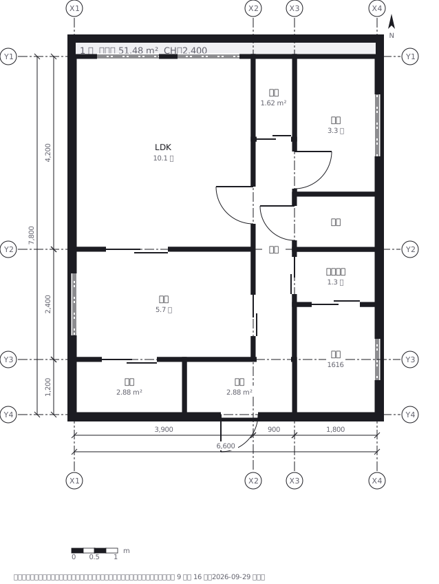 A two-bedroom apartment plan with room dimensions, which way each door swings, and where the wet rooms and storage sit
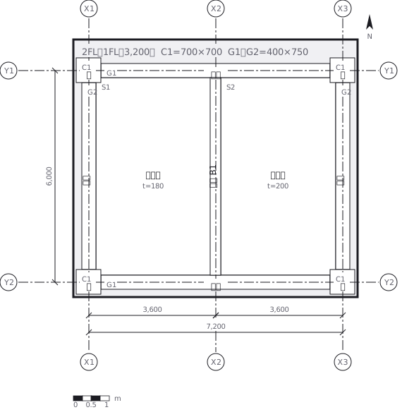 A reinforced concrete framing plan for a second floor, with the grid lines and the mark of every column, girder, beam and slab
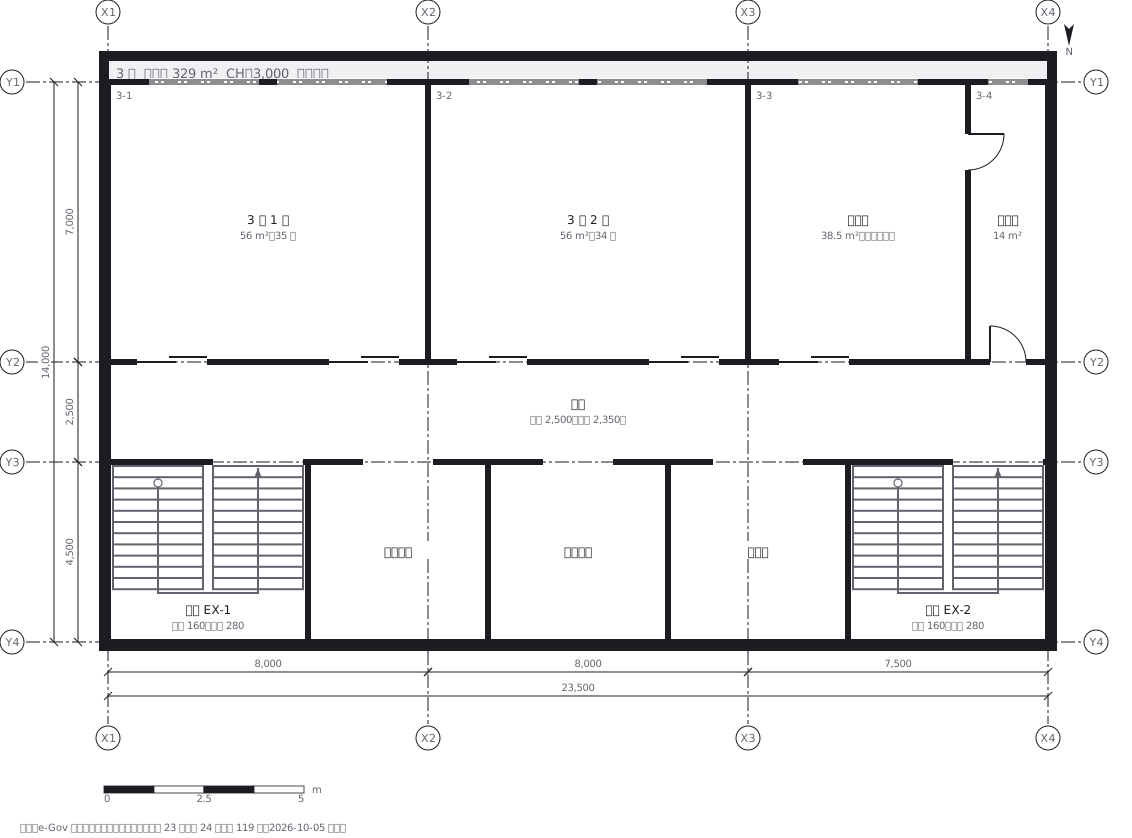 School floor plan (walls, door swings, grid lines, dimensions)
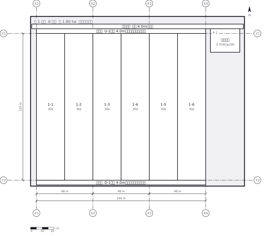 A farmland consolidation plan laying out 30-are plots, with the irrigation channels, the drainage channels and the farm roads that serve them
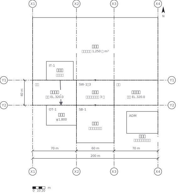 The plan of a concrete gravity dam: the body, the spillway, the intake works and the access road for maintenance
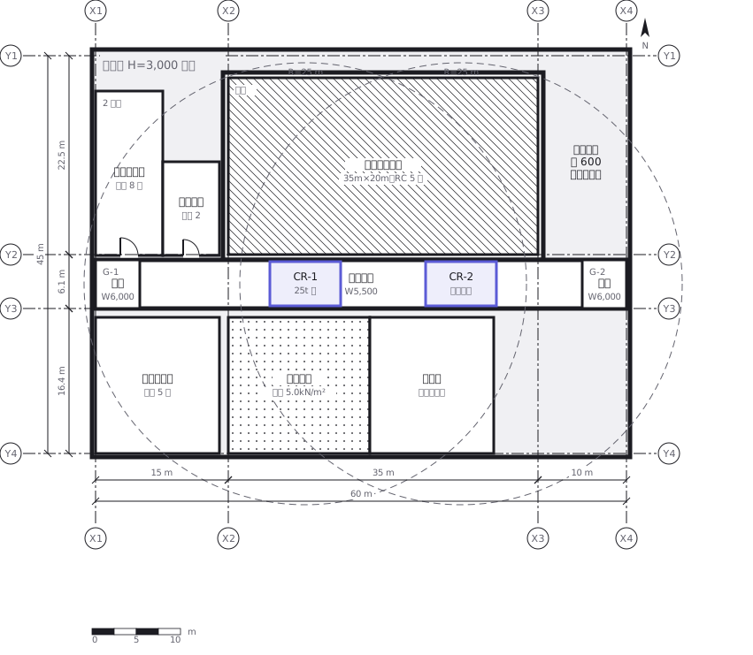 Site logistics plan with the crane radius
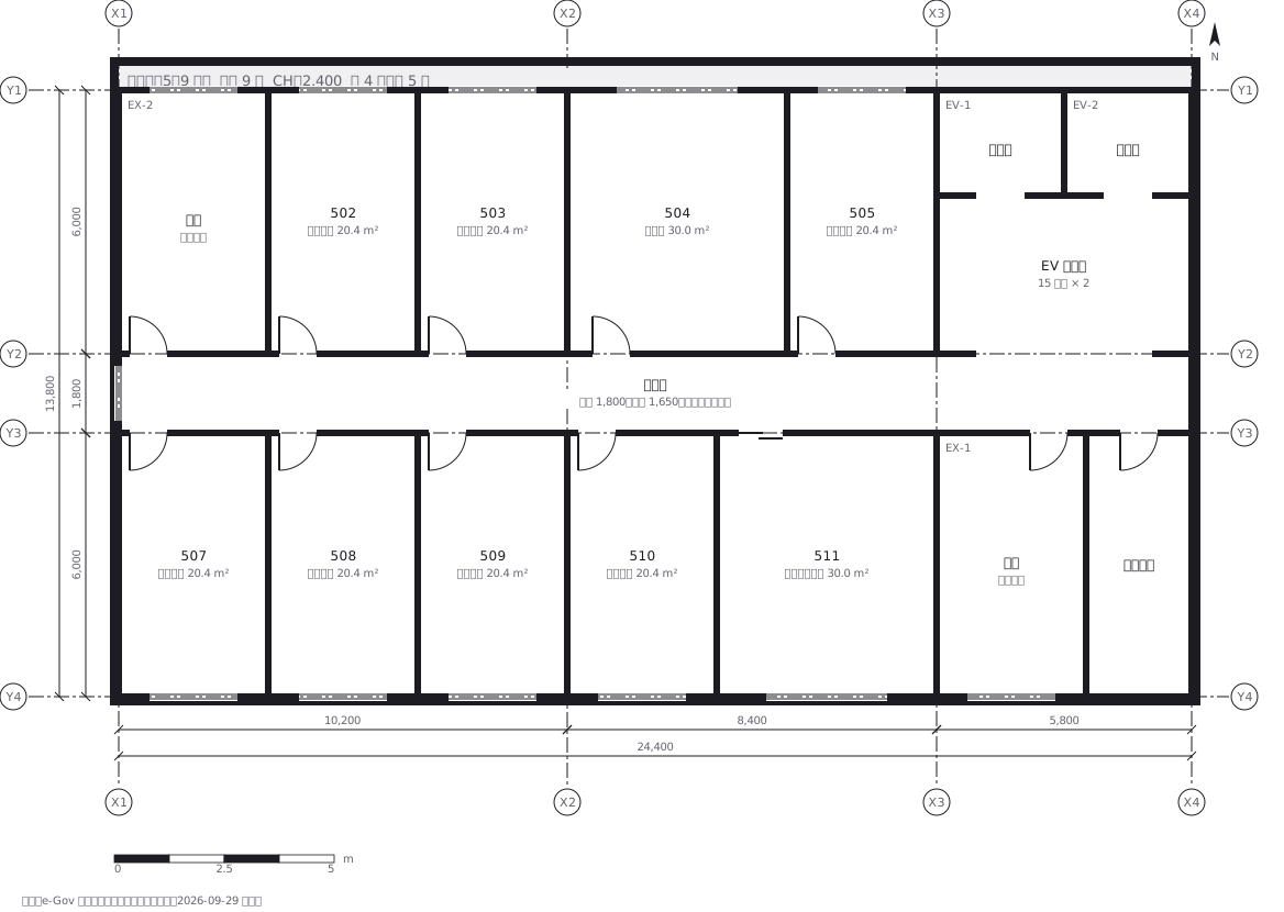 The typical floor of a business hotel with nine rooms, a central corridor, two direct stairs, and two lifts with their hall
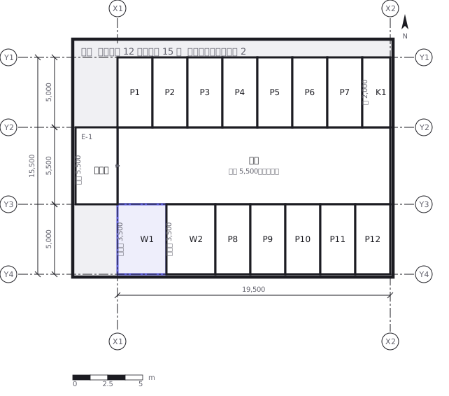 A surface car park set out for fourteen cars, with bay dimensions, aisle width and where the entrance and exit sit