Building and civil
Welding symbols (JIS Z 3021:2016)
A welding symbol is read together with its arrow: below the reference line means the arrow side, above it means the other side, so the same symbol welds the opposite face if the arrow moves
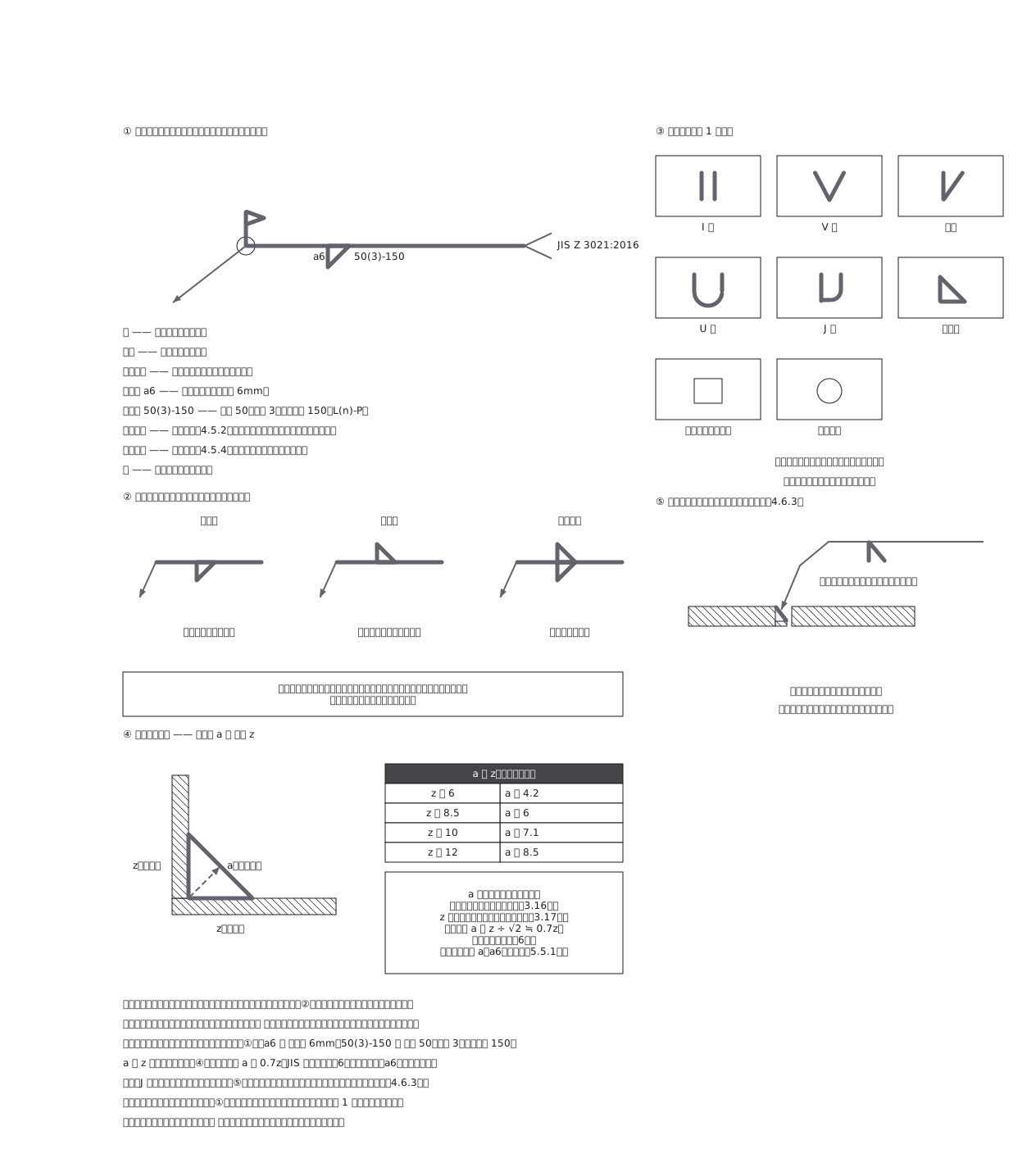
This drawing comes from one YAML file. No shape was moved by hand.
Notes in the source (in Japanese)
基線の上下が、どちらの面を溶接するかを言う。下が矢の側、上がその反対側。上下ともに書けば両側。だから記号は、矢をどこへ当てたかと組でしか読めない。
寸法は基本記号の左が断面、右が長さ。a6 50(3)-150 なら、のど厚 6mm・長さ 50・個数 3・中心間隔 150(表 5 の L(n)-P)。ISO 2553:2013 の System A は n×l(e) と書き、e はすき間で中心間隔ではない。JIS は System B。
のど厚 a と脚長 z は別の寸法(3.16 / 3.17)。等脚なら a = z ÷ √2 ≒ 0.7z。JIS では脚長は文字を付けずに「6」、のど厚は「a6」と書く(5.5.1)。「a6」と「6」では大きさが 1.4 倍違う。
レ形・J 形は片方の材だけを削るので、矢を折って、削る材を指す(4.6.3)。矢と基線の交点の丸が全周溶接、旗が現場溶接。記号の決まりは JIS Z 3021:2016 の本文(ISO 2553:2013 の System B に対応)で確かめた。
Source (YAML)
examples/gallery/242-溶接記号.zumen.yaml
More in this field
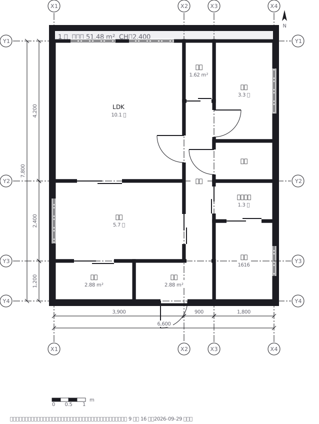 A two-bedroom apartment plan with room dimensions, which way each door swings, and where the wet rooms and storage sit
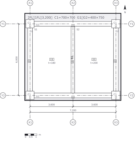 A reinforced concrete framing plan for a second floor, with the grid lines and the mark of every column, girder, beam and slab
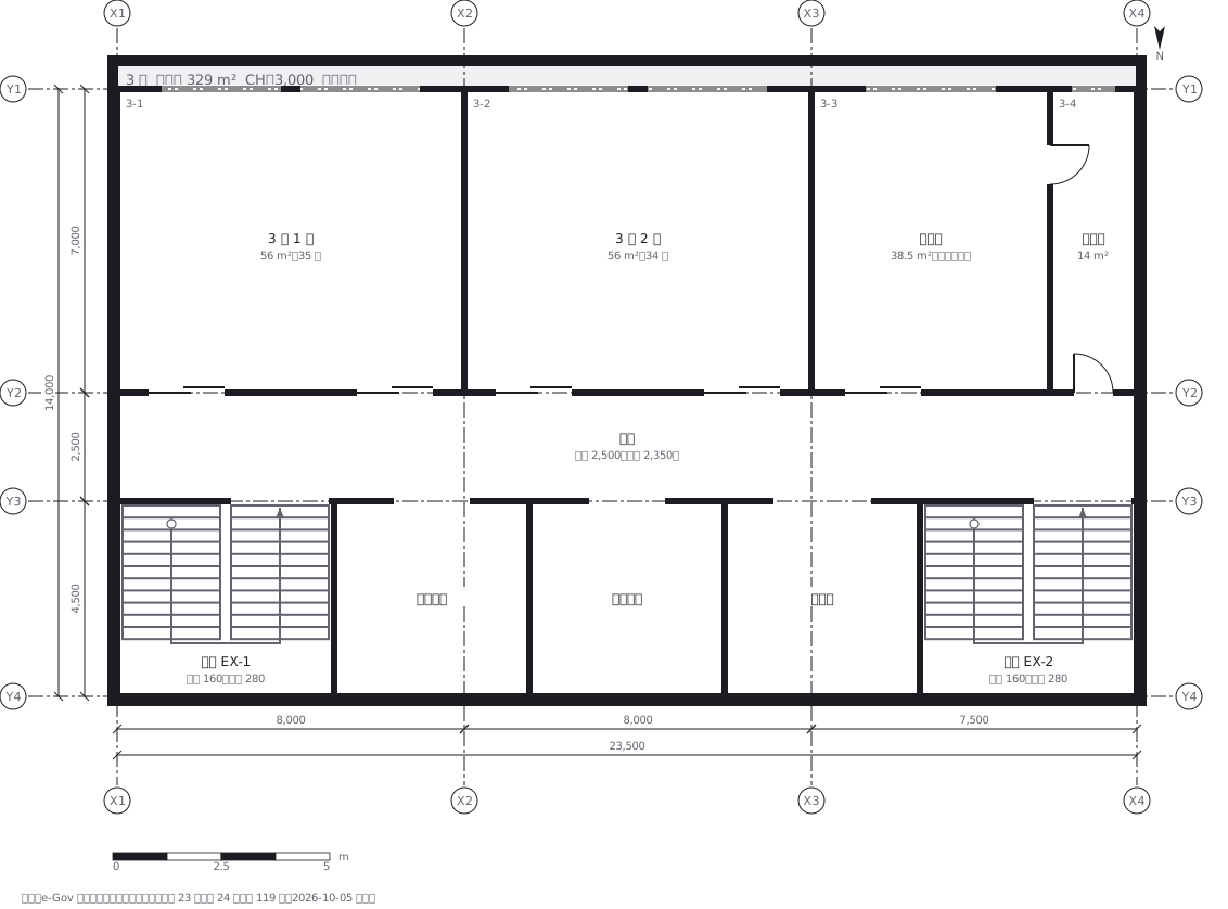 School floor plan (walls, door swings, grid lines, dimensions)
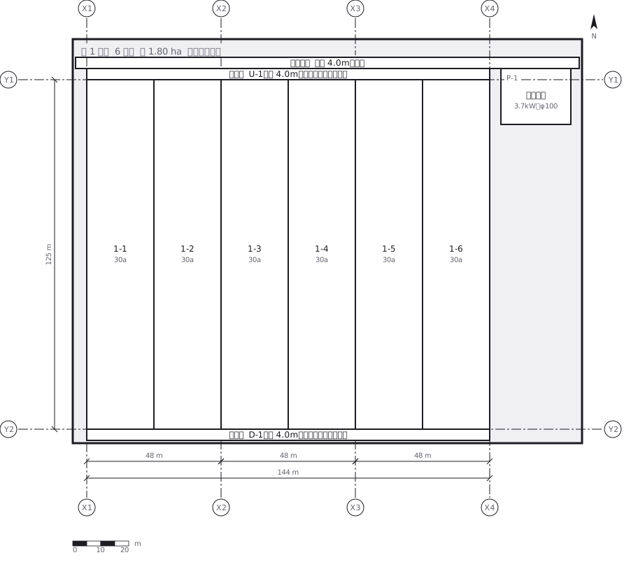 A farmland consolidation plan laying out 30-are plots, with the irrigation channels, the drainage channels and the farm roads that serve them
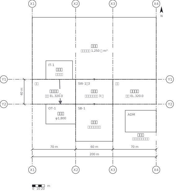 The plan of a concrete gravity dam: the body, the spillway, the intake works and the access road for maintenance
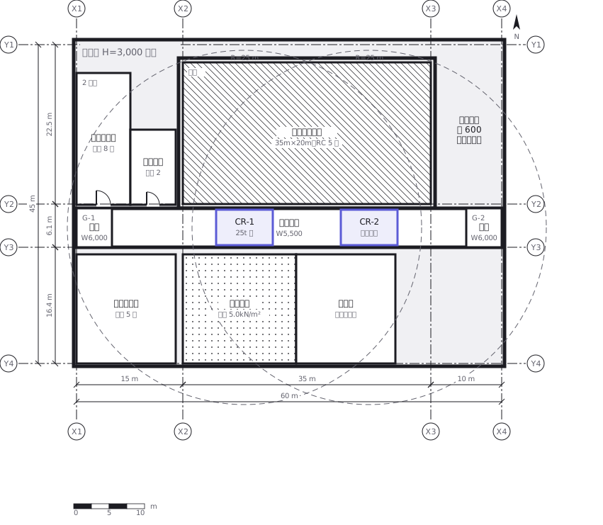 Site logistics plan with the crane radius
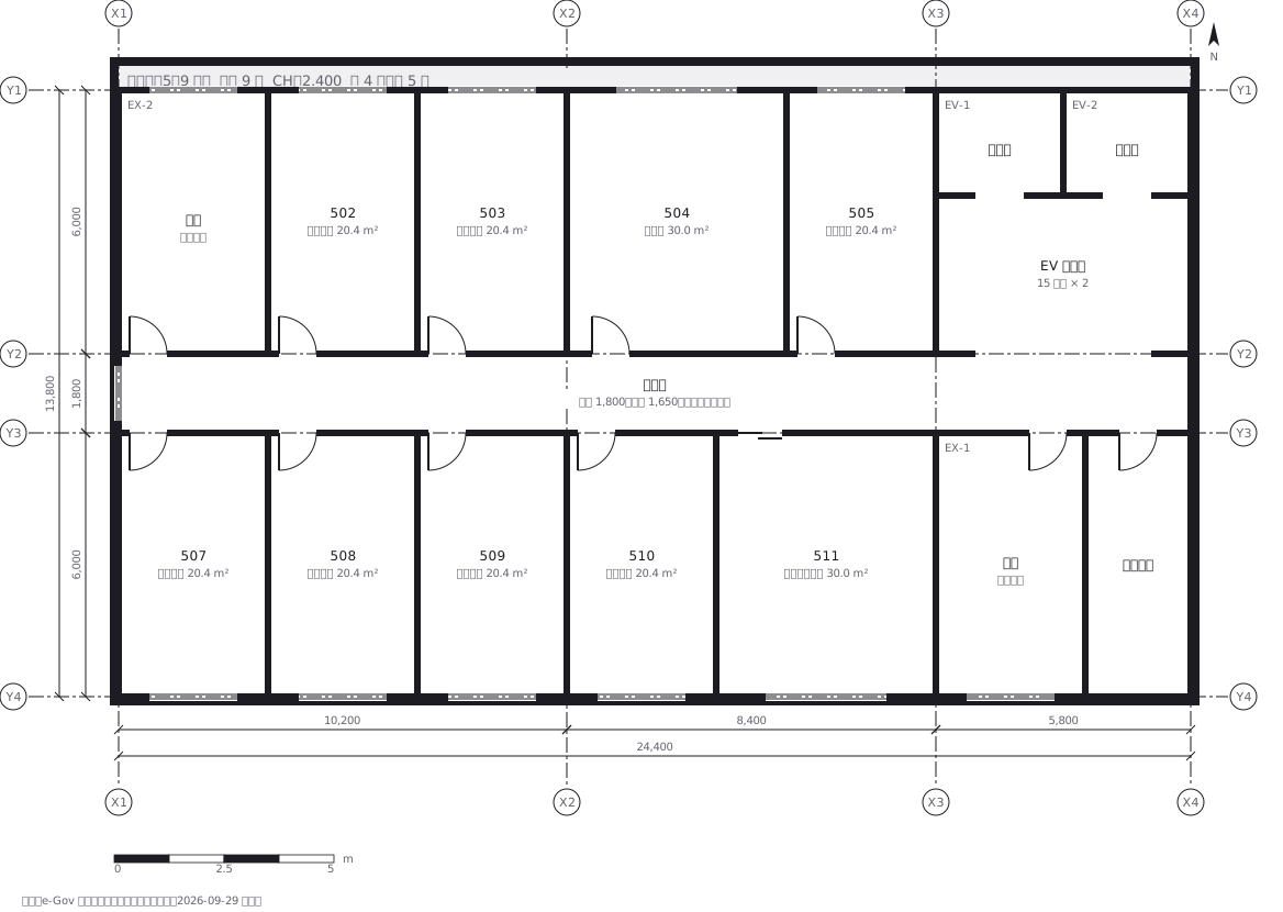 The typical floor of a business hotel with nine rooms, a central corridor, two direct stairs, and two lifts with their hall
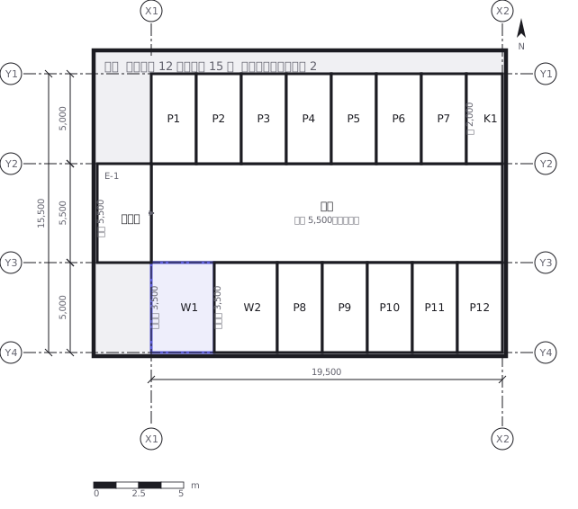 A surface car park set out for fourteen cars, with bay dimensions, aisle width and where the entrance and exit sit